


B-7
Cisco MGX 8800/8900 Series Hardware Installation Guide
Releases 2 - 5.2, Part Number OL-4545-01, Rev. H0, May 2006
Appendix
Control and Clock Cabling
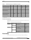
Note Make sure that the 100-ohm termination is selected when you configure the clocks for T1. You need to
connect only the RX Ring, the RX Tip, and the Ground (pins 4, 5, and 6).
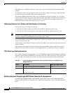
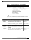
Table B-6 shows the pin assignment for the RJ-48 BITS clock connector.
Connect the External Clock
The section provides the following installation procedures for connecting the external clock:
• “Connect the External Clock Using an RJ-45 Connection” section on page B-7
• “Connect the External Clock Using a Wire-Wrap Adapter” section on page B-7
Connect the External Clock Using an RJ-45 Connection
Complete the following steps to connect the external clock.
Tip We recommend that you label each data cable at both ends to identify its source and destination.
Step 1 Verify that you have a PXM-UI-S3 or PXM-UI-S3/B back card installed in slots 7 and 8 in the upper rear
bay of the switch. (In an MGX 8830 and MGX 8830/B, these cards would be in slots 1 and 2.)
Step 2 Connect the cable connector to the EXT CLK 1 port on the user interface back card.
Step 3 Connect the other end of the cable to the clock source.
Step 4 Repeat Step 1 through Step 3 as necessary for each external clock connection.
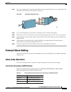
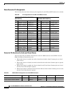
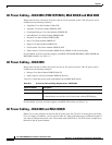
Connect the External Clock Using a Wire-Wrap Adapter
The optional RJ-45 to wire-wrap adapter (PXM-WIREWRAP=) connects an external building integrated
timing supply (BITS) clock source to the PXM-UI-S3 or PXM-UI-S3/B using s wire-wrap connection
instead of an RJ-45 connection (see Figure B-2).
Table B-6 Pin Assignments for the RJ-48 BITS Clock Connector
Pin No. Signal
1TX ring
2 TX tip
3 Ground
4RX ring
5 RX tip
6 Ground
1
1. No connection on the MGX 8830 and MGX 8830/B
7 TTP ring
8 TTP tip