


5-110
Cisco MGX 8800/8900 Series Hardware Installation Guide
Releases 2 - 5.2, Part Number OL-4545-01, Rev. H0, May 2006
Chapter 5 Installing the Cisco MGX Switch or Gateway
Installing the MGX 8830 or MGX 8830/B Switch
• “Remove the Back Cards from an APS Assembly” section on page 5-111
• “Remove the DC PEM(s)” section on page 5-112
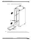
• “Install the Switch in the Rack or Cabinet” section on page 5-112
• “Reinstall the APS Assembly” section on page 5-114
• “Reinstall the Back Cards” section on page 5-115
• “Reinstall the DC PEM(s)” section on page 5-117
• “Reinstall the Front Cards” section on page 5-117
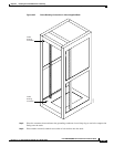
Tip If a component requires more than two screws for installation in the rack or cabinet, install the two
bottom screws first.
Prepare for Installation
Review the following guidelines before installation begins:
• Before removing any cards, modules, or assemblies, it is recommended that you carefully note and
write down their location or slot number in the chassis.
• Verify that your ESD grounding wrist strap is properly connected. See the “Preventing ESD
Damage” section on page 3-7 for detailed information about ESD procedures.
Remove the Front Cards
Complete the following steps to remove front cards from the chassis.
Note The card should slide in and out with only slight friction on the adjacent board’s EMI gaskets. Do not
force the card. Investigate any binding.
Each single-height front card has an extractor lever at the left of the faceplate to secure it in the card
cage. Each double-height front card has an extractor lever at both the left and right of the faceplate.
Caution Do not use a power screwdriver on captive screws.
Caution When extracting a front card, keep the card level until it is completely extracted from the chassis. Do not
allow the front cards to drop against the cards below them. This could damage components on the cards.
Step 1 Connect a grounding strap to the ESD grounding jack or to the equipment rack.
Step 2 Place the MGX 8830 switch on a flat and stable surface (for example, the floor).
Step 3 Open the front door of the switch, as necessary.
Step 4 Record the location of all of the cards before you remove them.
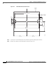
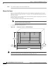
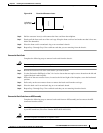
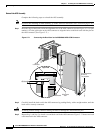
Step 5 Insert and press the flat-head tip of the 3-in-1 tool into the slot(s) of the extractor lever(s) at the left (and
right) of the front card until the latch(es) springs open. Figure 5-70 shows the location of the lever slot
in relation to the left side of the front card.