


2-36
Cisco MGX 8800/8900 Series Hardware Installation Guide
Releases 2 - 5.2, Part Number OL-4545-01, Rev. H0, May 2006
Chapter 2 Illustrated Card List for MGX Switches and the MGX 8880 Media Gateway
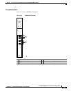
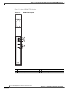
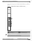
Front Cards
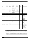
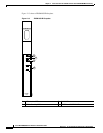
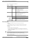
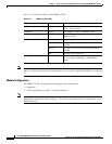
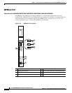
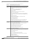
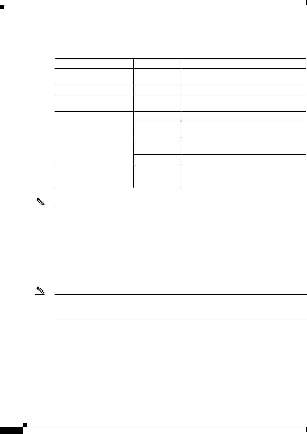
Table 2-17 describes the LEDs on the FRSM-12-T3E3s.
Note For information on FRSM-12-T3E3 software features and configurations, refer to the Frame Relay
Software Configuration Guide and Command Reference for the Cisco MGX 8850 FRSM12 Card, Release
3.
Module Configurations
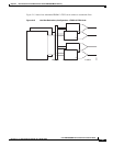
The FRSM-12-T3E3 card supports the following module configurations:
• Standalone.
• Card set redundancy (Y-cable)—T3 and E3 interfaces.
Note As of MGX Release 4, T3 support is operational and E3 is planned for a future release. For module
configuration information, refer to Chapter 4, “Planning for Card Redundancy, Line Redundancy, and
Bulk Distribution”.
Table 2-17 FRSM-12-T3E3 LEDs
LED Status Description
ACT Green The FRSM-12-T3E3 card set (front card and back
card) is in active state.
STANDBY Yellow The FRSM-12-T3E3 is in Standby mode.
FAIL Red A failure has been detected on the
FRSM-12-T3E3.
PORT 1 through PORT 12 Green The port is active with no alarms detected.
Red The port is active and a local alarm has been
detected.
Yellow The port is active and a remote alarm has been
detected.
Off The port is not configured.
T3 or E3 Green The FRSM-12-T3E3 card set is operating in either
T3 or E3 mode (depending on which LED is
green).