


1-36
Cisco MGX 8800/8900 Series Hardware Installation Guide
Releases 2 - 5.2, Part Number OL-4545-01, Rev. H0, May 2006
Chapter 1 Product Overviews
Cisco MGX 8950 Switch
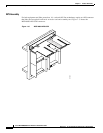
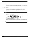
MGX 8950 Card Compartment
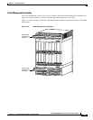
The MGX 8950 switch has 32 single-height slots in a compartment card cage that holds cards and
modules. Some single-height slots can be converted to double-height slots by removing the midrail
dividers.
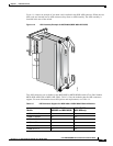
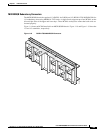
MGX 8950 Slot Assignments
Each slot on the front of the switch is numbered and has a corresponding slot located on the back of the
switch. There are 32 front card slots and 32 back card slots. Slots 1 through 16 are in the top bay and
slots 17 through 32 are in the bottom bay of the switch.
Table 1-3 lists module slot assignments for the MGX 8950 switch.
MGX 8950 Cards Supported
Table 1-3 lists cards supported in a MGX 8950 switch. The MGX 8950 switch was introduced in MGX
Release 2.1.
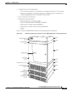
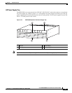
MGX 8950 System Hardware Components
This section provides details about the following MGX 8950 switch hardware components;
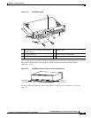
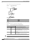
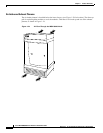
• AC Power Supply Tray, page 1-37
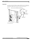
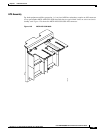
• Extender Card, page 1-39
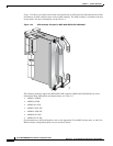
• Air Intake and Exhaust Plenums, page 1-40
• APS Assembly, page 1-41
• Cable Management Assembly, page 1-43
• DC Power Entry Module, page 1-44
• Lower and Upper Fan Trays, page 1-45