


2-122
Cisco MGX 8800/8900 Series Hardware Installation Guide
Releases 2 - 5.2, Part Number OL-4545-01, Rev. H0, May 2006
Chapter 2 Illustrated Card List for MGX Switches and the MGX 8880 Media Gateway
Back Cards
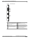
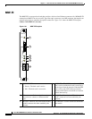
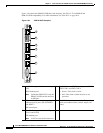
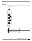
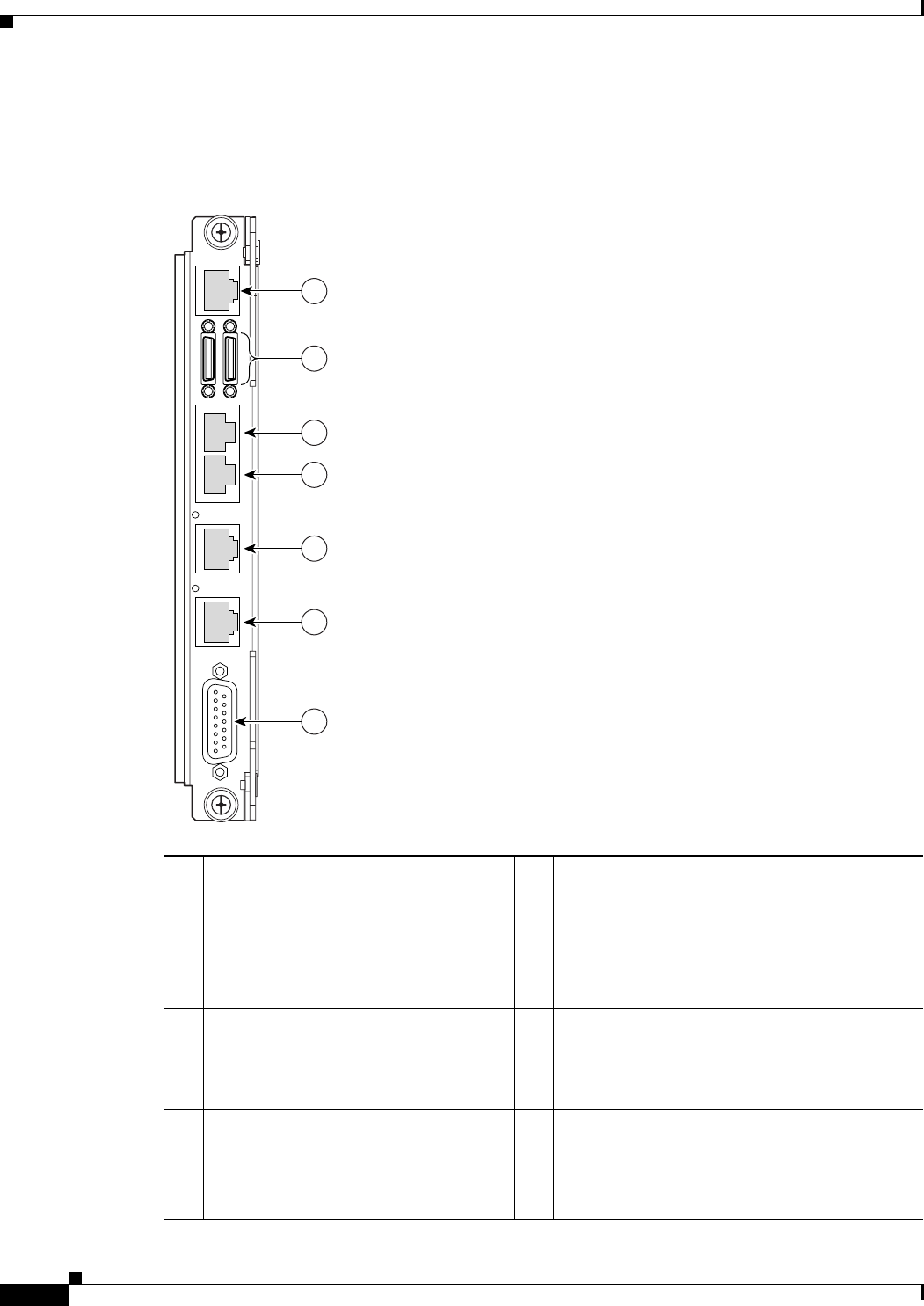
Figure 2-64 shows the PXM-UI-S3/B back card faceplate. See Table 2-22 for PXM1E and
PXM-UI-S3/B compatibility. For cable information, see Table B-14 on page B-14.
Figure 2-64 PXM-UI-S3/B Faceplate
1 An RJ-45 receptacle for the control port
(CP)
PNNI modem port.
Note Unlike the PXM-UI-S3 card, the
PXM-UI-S3/B card doe not have
an MP port.
4 Two RJ-48 external T1/E1 clock ports and LEDs
(EXT CLK 1 and EXT CLK 2)
• Green—The clock is active.
• Off—The clock is either inactive or not
provided.
2 Miniature D connectors to support two
additional serial ports (SP) for PORT 1
and PORT 2
IOS control port
5 One DB-15 female connector ALARM port for
visual and audible alarms (critical, major, and
minor)
3 Two RJ-45 receptacles for the LAN ports
(LAN1 and LAN2)
IOS modem port
Note LAN2 is reserved for future use.
80666
PXM
UI-S3/B
1
7
3
4
5
6
E
X
T
C
L
K
2
A
L
A
R
M
E
X
T
C
L
K
1
L
A
N
2
L
A
N
1
S
P
P2 P1
C
P
2