


5-73
Cisco MGX 8800/8900 Series Hardware Installation Guide
Releases 2 - 5.2, Part Number OL-4545-01, Rev. H0, May 2006
Chapter 5 Installing the Cisco MGX Switch or Gateway
Installing the MGX 8950 Switch
Step 8 Repeat Step 2 through Step 7 for each back card that you are reinstalling in the chassis.
Step 9 Install blank faceplates over any empty slots.
Reinstall the Front Cards
Note All cards must be fully seated in the chassis. When installing the front card, apply even pressure to the
top and bottom of the faceplate to make sure that the card is fully seated.
The card should slide in and out with only slight friction on the adjacent board’s EMI gaskets. Do not
force the card. Investigate any binding.
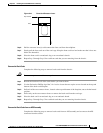
Each single-height front card has an extractor lever at the top of the faceplate to secure it in the card cage.
Each double-height front card has an extractor lever at both the top and the bottom of the faceplate.
Caution If the AXSM-1-2488 or AXSM-1-2488/B front cards are installed with incorrect back cards, damage to
the cards might result.
Caution To prevent damage to components on the bottom side of a card, support the faceplate and keep the card
level while sliding it into the switch.
Warning
Blank faceplates and cover panels serve three important functions: they prevent exposure to
hazardous voltages and currents inside the chassis; they contain electromagnetic interference (EMI)
that might disrupt other equipment; and they direct the flow of cooling air through the chassis. Do not
operate the system unless all cards, faceplates, front covers, and rear covers are in place.
Statement 1029
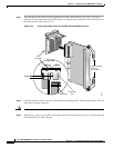
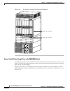
Complete the following steps to reinstall a front card in the MGX 8950 switch:
Step 1 Refer to the notes you made when you recorded the location of each card to ensure that the cards are
installed in the correct slots. For slot assignments for your system, refer to the “MGX 8950 Card
Compartment” section on page 1-36.
Step 2 See the “General Card Installation Guidelines” section on page 3-8 to verify that there are no bent pins,
bent dividers, or damaged connectors on the back cards.
Step 3 Verify that the extractor lever(s) are in the unlatched position.
Step 4 Position the front card over the appropriate slot and align the front card edge with the slot guides (top
and bottom) in the chassis.
Step 5 Lift up and out on the extractor lever(s) and gently apply pressure to the faceplate while pushing the front
card into the slot.
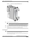
Step 6 Once the front card is installed in the chassis, apply even pressure to the top and bottom of the faceplate
to fully seat the front card.
Step 7 Press down on the extractor lever(s) until they latch to secure the front card.