


1-50
Cisco MGX 8800/8900 Series Hardware Installation Guide
Releases 2 - 5.2, Part Number OL-4545-01, Rev. H0, May 2006
Chapter 1 Product Overviews
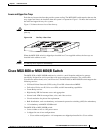
Cisco MGX 8830 or MGX 8830/B Switch
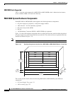
MGX 8830 Cards Supported
Table 1-3 lists the cards supported in a MGX 8830 or MGX 8830/B switch. Abbreviated card names,
such as AUSM or MMC, are listed in the Glossary.
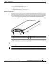
MGX 8830 System Hardware Components
Each MGX 8830 or MGX 8830/B switch supports the following hardware components:
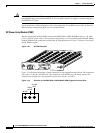
• AC power supply tray (optional)—with power supply modules
• APS connector—for line redundancy (optional)
• DC power entry module (PEM)
• Fan tray
• 1:N Redundancy Connector (RCON)—MGX 8830/B only (optional)
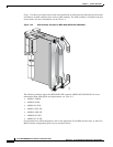
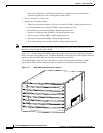
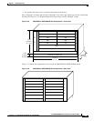
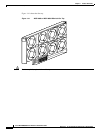
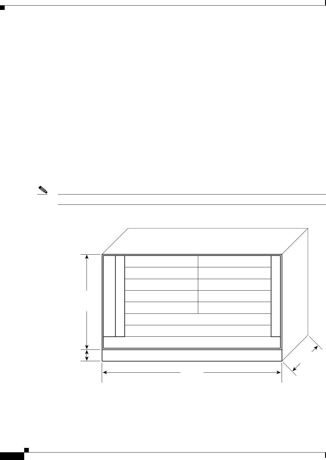
Figure 1-34 shows the hardware components that are visible from the front, which include the optional
AC power supply tray at the bottom and fan tray at the left. The switch can have an optional front door
installed (as shown in Figure 1-31).
Note For the switch to be EMI compliant, blank faceplates must be installed to cover any empty slots.
Figure 1-34 Hardware Component Locations for a MGX 8830 or MGX 8830/B Switch—Front View
This section provides details about the following MGX 8830 or MGX 8830/B system hardware
components:
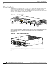
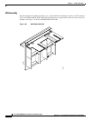
• AC Power Supply Tray, page 1-51
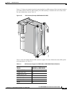
• APS Assembly, page 1-52
SRM
7
6
5
4
3
2
1
SRM
SM SM
SM SM
SM SM
SM SM
F
A
N
T
R
A
Y
7 RU
(12.25 in.,
31.1 cm.)
17.72 in.
(45 cm.)
1 RU
(1.75 in.,
4.5 cm.)
PXM
PXM
Optional AC power tray
14
13
12
11
10
23.5 in.,
(59.7 cm.)
38375
8
9