


3-43
Cisco MGX 8800/8900 Series Hardware Installation Guide
Releases 2 - 5.2, Part Number OL-4545-01, Rev. H0, May 2006
Chapter 3 Preparing for Installation
Site Requirements for a MGX 8830 or MGX 8830/B Switch
Seismic Anchoring
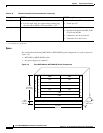
In order for you to secure a Cisco-supplied cabinet, the holes in the upper and lower corners
accommodate 3/8-inch or 1/2-inch bolts. Also, you can buy an optional stability plate with the Cisco
cabinet. The stability plate is bolted to the floor, and then the Cisco cabinet is bolted to the stability plate.
See Chapter 5, “Installing the Cisco MGX Switch or Gateway” for stability plate installation
instructions.
Shock
For nonoperating mechanical shock and for equipment weighing more than 100 pounds, the peak
acceleration will be between 20 to 25 G.
For operating mechanical shock, the minimum velocity change is 0.66 meters per second with an
effective free fall drop height of 13 mm for Mechanical Design Validation Test (MDVT) and an effective
free fall drop height of 25 mm for Network Equipment Building Standards (NEBS) with no velocity
change specified.
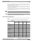
Vibration
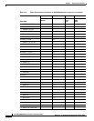
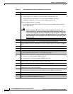
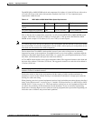
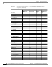
Table 3-16 describes the Cisco recommendations for vibration conditions.
Table 3-16 Vibration Condition Recommendations
Category NEBS Description MDVT Description
Earthquake
• No damage to the switch when tested to earthquake
waveform.
• 75-mm maximum single amplitude deflection.
• Frame-level natural mechanical resonant frequency > 2
Hz.
• Frame-level natural mechanical resonant frequency > 6
Hz.
• Product must function before and after each axis.
• Product must operate without loss of service during
earthquake testing.
None
Office
• 3 axis swept-sine.
• 5 Hz to 100 Hz to 5 Hz.
• 0.1 G, 0.1 octaves/min.
• 0.41 Grms, 3 to 500 Hz
• Spectral break points of 0.0005 G
1
/Hz
at 10 Hz and 200 Hz
• 5 dB/octave roll-off at each end
• 2 hrs per axis of operation