


5-67
Cisco MGX 8800/8900 Series Hardware Installation Guide
Releases 2 - 5.2, Part Number OL-4545-01, Rev. H0, May 2006
Chapter 5 Installing the Cisco MGX Switch or Gateway
Installing the MGX 8950 Switch
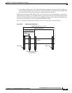
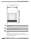
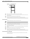
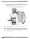
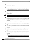
Figure 5-41 Front Card Extractor Lever
Step 6
Pull the extractor lever(s) to disconnect the front card from the midplane.
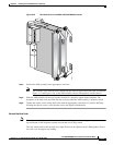
Step 7 Gently pull the front card out of the card cage. Keep the front card level and make sure that it does not
hit the one beneath it.
Step 8 Place the front card in an antistatic bag or on an antistatic bench.
Step 9 Repeat Step 5 through Step 8 for each front card that you are removing from the chassis.
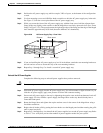
Remove the Back Cards
Complete the following steps to remove back cards from the chassis:
Caution Do not use a power screwdriver on captive screws.
Step 1 Record the location of all of the cards before you remove them.
Step 2 Use the flat-head or Phillips tip of the 3-in-1 tool to loosen the two captive screws located on the top and
bottom of the back card faceplate.
Step 3 Pull each of the two extractor levers, located at the top and bottom of the faceplate, out to the horizontal
position.
Step 4 Pull evenly on the two extractor levers to remove the back card from the card cage.
Step 5 Place the back card in an antistatic bag or on an antistatic bench.
Step 6 Repeat Step 2 through Step 5 for each back card that you are removing from the chassis.
Remove the Back Cards from an APS Assembly
Complete the following steps to remove back cards from an APS assembly and to remove the APS
connector from the switch:
Top of card
Slot
H8293