


5-107
Cisco MGX 8800/8900 Series Hardware Installation Guide
Releases 2 - 5.2, Part Number OL-4545-01, Rev. H0, May 2006
Chapter 5 Installing the Cisco MGX Switch or Gateway
Installing the MGX 8830 or MGX 8830/B Switch
Prepare for Rack Installation
The minimum distance between left and right mounting rails (as you face the rack) must be 17.75 inches
or 45.08 cm. (Some 19-inch racks have only 17.50 inches between the rails.) The width of the
components, such as the card cage and fan tray, is 17.72 inches.
When installing a MGX 8830 system in a 19-inch rack, adhere to the following guidelines:
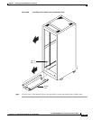
• Open-rack configuration—The switch and optional AC power supply tray need to be mid-mounted
in the rack. Brackets for that purpose are included with the system.
• Cisco cabinet configuration—The switch and optional AC power supply tray are shipped
front-mounted in the enclosure, and the rear of each component is supported by a rear bracket.
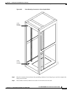
When you are installing a MGX 8830 system in a 23-inch rack, the switch and optional AC power supply
tray need to be mid-mounted in the rack. You need special mounting brackets to mid-mount the
components in a 23-inch rack (mounting kit, Cisco Part Number MGX-8830-MNT23).
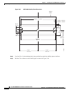
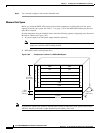
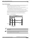
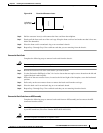
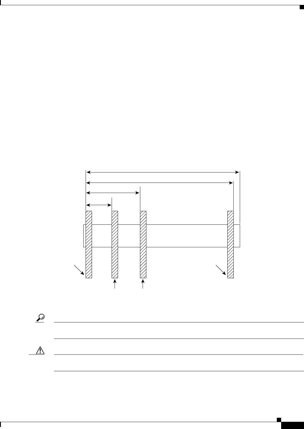
Figure 5-69 shows the mounting rail distances for front, middle, and rear mounting rails.
Figure 5-69 Mounting Rail Distances
Tip If a component requires more than two screws for installation in the rack or cabinet, install the two
bottom screws first.
Caution Make sure that mounting the equipment does not create a hazardous condition due to uneven mechanical
loading. The equipment rack should be securely supported.
Module
Rear rail
5.0 in.
10.0 in.
19.86 in.
MGX 8230 depth 23.5 in.
Allowable intermediate
rail positions
Front rail
47074