


5-133
Cisco MGX 8800/8900 Series Hardware Installation Guide
Releases 2 - 5.2, Part Number OL-4545-01, Rev. H0, May 2006
Chapter 5 Installing the Cisco MGX Switch or Gateway
Installing the Ferrite Bead on the PXM-UI-S3/B Card
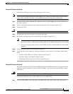
Step 1 If your switch has an (optional) front door, verify that the door is installed and closed and that each
empty slot is covered by a blank faceplate.
Step 2 Install the ferrite bead if needed. Refer to “Installing the Ferrite Bead on the PXM-UI-S3/B Card”
section on page 5-133.
Note Refer to the appropriate software configuration guide for your switch and your release to configure
general switch features.
Installing the Ferrite Bead on the PXM-UI-S3/B Card
The PXM-UI-S3/B back card is used in the following MGX chassis:
• MGX 8850 (PXM45), with a Model PXM45/C card
• MGX 8850 (PXM1E)
• MGX 8850/B
• MGX 8830 (PXM1E)
• MGX 8830/B
• MGX 8950, with a Model PXM45/C card
• MGX 8880
The ferrite bead kit is part MGX-FBK. The kit includes seven ferrite beads and installation instructions
packaged in bubble wrap. Each ferrite bead is part 36-0217-01. The installation instructions, which
mirror this section, are part 78-16699-01. The ferrite bead kit ships with the PXM-UI-S3/B back card.
Caution To keep EMI to a minimum, and for the PXM-UI-S3/B back card to be CE and FCC Class A compliant,
you must install a ferrite bead on each cable that attaches to the PXM-UI-S3/B back card with an RJ
connector. Use shielded cable.
How to Install the Ferrite Bead
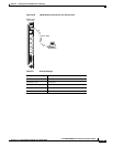
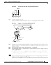
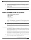
Cables that attach to the PXM-UI-S3/B back card with an RJ connector require a ferrite bead—that is,
cables leading to RJ connectors 1, 3, 4, 5, and 6 in Figure 5-86.
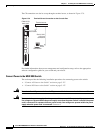
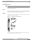
The ferrite bead locking mechanism is a plastic, snap shut design located in three places along its length
(see Figure 5-87). To install the ferrite bead:
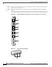
Step 1 If the ferrite bead is open, skip to Step 2.
If the ferrite bead is closed, place the bead on a flat surface, insert a small flat-blade screwdriver into the
recessed area under each of the three locking tabs (item 1 in Figure 5-86), and carefully pry outward to
unlock the mechanism.
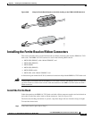
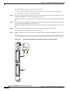
Step 2 Place the open ferrite bead on the cable 1 to 6 inches (2.54 cm to 15.24 cm) from the end to be connected
to the RJ connectors located on the PXM-UI-S3/B back card (see Figure 5-87).