


1-72
Cisco MGX 8800/8900 Series Hardware Installation Guide
Releases 2 - 5.2, Part Number OL-4545-01, Rev. H0, May 2006
Chapter 1 Product Overviews
Cisco MGX 8880 Media Gateway
For information on APS software configuration, refer to the software configuration guide that matches
your MGX switch name and release. The “Obtaining Documentation” section explains how to find these
documents online
DC Power Entry Module (PEM)
The Cisco MGX 8880 gateway can accept power from a –48 VDC (–42 to –56 VDC) source that
connects to one (primary) or two (secondary/redundant) –48 VDC PEMs. Each DC PEM must be
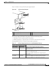
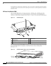
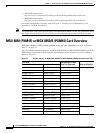
connected to a dedicated 60 A regulated source. Figure 1-51 shows a close-up of the DC PEM faceplate.
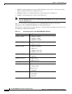
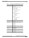
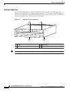
Figure 1-51 DC PEM Faceplate
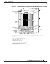
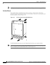
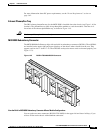
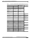
For a DC-powered system, the DC PEMs are installed at the back of the air intake plenum. If you install
only one DC PEM, install it on the right, as viewed from the rear of the air intake plenum.
(See Figure 1-52.)
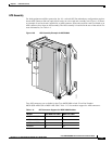
Figure 1-52 DC PEMs Installed in Back of the Air Intake Module
1 Two-position circuit breaker. The positions
are Off and On.
4 Plastic cover.
2 J1 output connector. 5 Terminal block 1 (DC input).
3 Green LED showing status of the DC PEM.
J1
-48V
OFF
ON
RTN
DC OK
84460
4
3
2
1
5
116505
Secondary
DC PEM
Primary
DC PEM