


3-19
Cisco MGX 8800/8900 Series Hardware Installation Guide
Releases 2 - 5.2, Part Number OL-4545-01, Rev. H0, May 2006
Chapter 3 Preparing for Installation
Site Requirements for the MGX 8850 or MGX 8850/B Switch
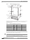
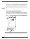
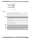
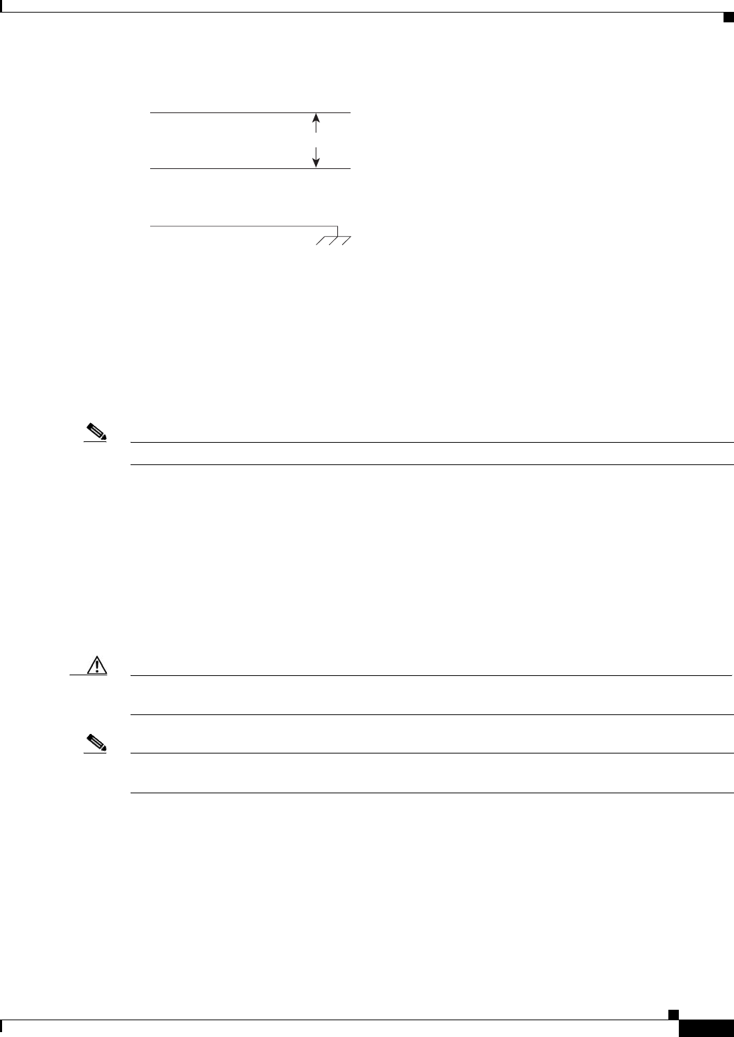
Figure 3-5 Schematic of AC Plug Wiring
DC Power
DC power is supplied to the MGX 8850 or MGX 8850/B switch through one or two DC PEMs. Each DC
PEM must be connected to a dedicated 60-A regulated source.
Each branch circuit must have a 60-A circuit breaker at the source. Wires connecting the PEMs to the
sources should be capable of carrying 60 A. A 6-AWG (10-square mm) copper wire is recommended.
Consult the local or national codes for conductor sizing for DC supply connections if necessary.
Note For more information about the DC PEM, see the “DC Power Entry Module” section on page 1-30.
DC power sources must be dedicated DC branch circuits. Each branch circuit must be protected by a
dedicated circuit breaker.
The circuit breaker must have a rated trip delay time greater than that of the MGX 8850 or MGX 8850/B
switch circuit breaker. The switch uses a 60-A, 1-pole circuit breaker with a short trip delay on each –48
V input. It is recommended that the site have a dedicated 60-A, 1-pole circuit breaker with a medium
trip delay at each branch circuit.
Connect the safety grounding wire to a solid earth ground. It is recommended that you use a ring terminal
lug to terminate the ground conductor at the ground stud. For details, see the “Bonding and Grounding
the Cisco MGX System” section on page C-8.
Caution The –48 VDC return, logical grounds, and safety grounds are connected to the equipment chassis;
therefore, you must use a low-impedance connector to connect the chassis ground to the earthing ground.
Note Connect the MGX 8850 or MGX 8850/B switch only to a –48 VDC source that complies with the SELV
requirements in UL 1950, IEC 950, EN 60950, and CSA C22.2 No. 950-95.
H8397
L2
L1
200 to 240 VAC