


5-140
Cisco MGX 8800/8900 Series Hardware Installation Guide
Releases 2 - 5.2, Part Number OL-4545-01, Rev. H0, May 2006
Chapter 5 Installing the Cisco MGX Switch or Gateway
First Time Power On Procedure for MGX Switches
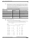
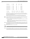
Top Fan Tray 7 >= 2000 RPM 3504 Normal
Top Fan Tray 8 >= 2000 RPM 3450 Normal
Top Fan Tray 9 >= 2000 RPM 3468 Normal
Bottom Fan Tray 1 >= 2000 RPM 0 Missing
Bottom Fan Tray 2 >= 2000 RPM 0 Missing
Bottom Fan Tray 3 >= 2000 RPM 0 Missing
Bottom Fan Tray 4 >= 2000 RPM 0 Missing
Bottom Fan Tray 5 >= 2000 RPM 0 Missing
Bottom Fan Tray 6 >= 2000 RPM 0 Missing
Bottom Fan Tray 7 >= 2000 RPM 0 Missing
Bottom Fan Tray 8 >= 2000 RPM 0 Missing
Bottom Fan Tray 9 >= 2000 RPM 0 Missing
+5V Input 4.850^ to 5.150^ VoltsDC 4.939 Informational
+3.3V Input 3.200^ to 3.400^ VoltsDC 3.259 Informational
+2.5V Input 2.425^ to 2.575^ VoltsDC 2.469 Informational
Calibration VDC 0x7e^ to 0x82^ Other 0x80 Informational
If the card comes up in backup boot, you need to copy firmware to the switch using FTP or TFTP.
Instructions for “Copying Software Files to the Switch” are in Appendix A of the Cisco MGX 8800/8900
Series Configuration Guide, Release 5.2 at
http://www.cisco.com/univercd/cc/td/doc/product/wanbu/8850px45/rel5/scg/mgx5scg.pdf. The
Configuration Guide also describes how to connect to the console port and initialize the switch.
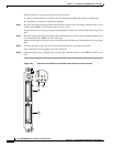
Step 8 Insert the standby PXM back cards, then the front card. Attach the console port cable to the back card.
Step 9 Through the console port connection, monitor the standby PXM card as it comes up to Standby mode.
When the card is in Standby mode, the prompt will appear like n.8.PXM.s>.
• If the standby PXM card comes up in backup boot, you might need to load software onto the PXM
card before proceeding.
• Check for alarms on the Standby PXM card from the Active PXM card. Use the display cards
(dspcds) command to ensure that the Active PXM card has no alarms (Alarms = none). Also check
that the Standby PXM card has no alarms.
Step 10 Put in the back cards (if any) for the Service Resource Modules (SRMs) for the primary PXM card. Then
insert the SRM front card, one at a time. See if the SRM comes up. The green light comes on when it’s
active and functional. Check that there are no alarms as each card goes through the hardware check, loads
firmware, and so on.
Step 11 Repeat Step 10 for the SRMs for the secondary PXM.
Note Refer to Table 5-9 for the proper slots in which to insert SRM cards.
Step 12 Install the remaining front and back cards, one card set at a time. Check operation at the console port for
each card, using display commands. As you install each card set, verify that it has come up properly.