


B-21
Cisco MGX 8800/8900 Series Hardware Installation Guide
Releases 2 - 5.2, Part Number OL-4545-01, Rev. H0, May 2006
Appendix
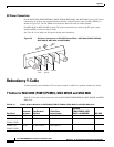
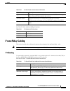
Frame Relay Cabling
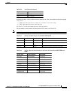
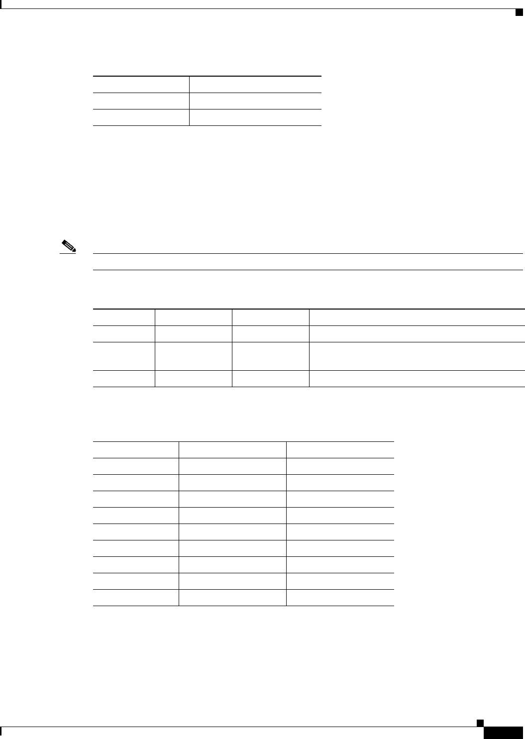
Each cable can have a male or female connector at the far end. Also, the available clock sources depend
on the mode:
• In DTE mode, the clock source is either line or ST (ST is a wire in the cable).
• In DCE mode, the clock source is the front card.
See Table B-27 for the relationship between cabling and modes.
For part numbers of the standard and non-standard 12IN1 cables, see Table B-28.
Note The cable type and part number are printed on a plastic band located near the smaller connector.
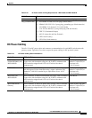
I_RXC/TXCE- Timing -
GND CCT Ground
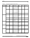
Table B-26 X.21 Signals (continued)
Signal Name
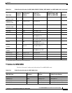
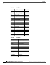
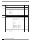
Table B-27 Cabling and Clock Sources for the MGX-FRSM-HS2/B
Mode Type of Cable Clock Source Mode of Far End
DTE DTE Line DCE (male or female connector at far end)
DCE DCE Internal (front
card)
DTE (male or female connector at far end)
DTE_ST DTE ST line DCE (male or female connector at far end)
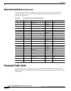
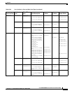
Table B-28 Cabling Types and Part Numbers for X.21 and V.35 Protocols for MGX-FRSM-xxxx
Cards
Type of Cable Far End Connector Part Number
X.21 DTE Male (standard) 72-1440-01
X.21 DCE Female (standard) 72-1427-01
V.35 DTE Male (standard) 72-1428-01
V.35 DTE Female (non-standard) 72-1436-01
V.35 DCE Female (standard) 72-1429-01
V.35 DCE Male (non-standard) 72-1437-01
V.35 DTE-DCE — 72-1441-01
Straight-through — 72-1478-01
Loopback plug — 72-1479-01