


2-74
Cisco MGX 8800/8900 Series Hardware Installation Guide
Releases 2 - 5.2, Part Number OL-4545-01, Rev. H0, May 2006
Chapter 2 Illustrated Card List for MGX Switches and the MGX 8880 Media Gateway
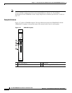
Front Cards
On an MGX 8850 (PXM1E or PXM45), the PXM card in slot 7 controls the SRM cards in slots 15 and
31. The PXM card in slot 8 controls the redundant SRM cards in slots 16 and 32.
On an MGX 8830, the PXM1E card in slot 1 controls the SRM card in slot 7. The PXM1E card in slot
8 controls the redundant SRM card in slot 14.
• Card set redundancy (Y-cable)—Redundant SRM cards must be placed in slots 15 and 16 for the
upper bay and 31 and 32 for the lower bay of the switch.
• 1+1 card and APS line redundancy (intercard)—OC-3c interfaces only.
Note Only the SRME supports APS.
Note For module configuration information, refer to Chapter 4, “Planning for Card Redundancy, Line
Redundancy, and Bulk Distribution”.
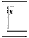
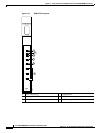
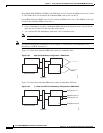
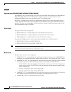
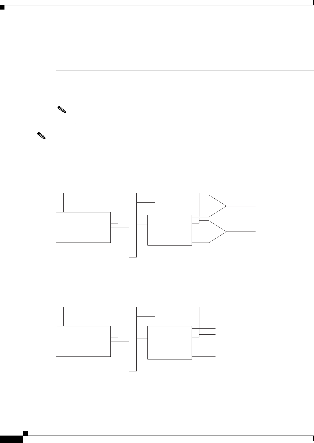
Figure 2-33 shows how redundant SRM cards connect to standalone lines.
Figure 2-33 Card Set Redundancy Configuration—SRM Cards
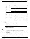
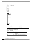
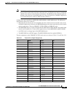
Figure 2-34 shows how redundant SRM cards connect to redundant APS lines.
Figure 2-34 1+1 Card and APS Line Redundancy Configuration—SRM Cards
SRM front cards
SRM back cards
80151
Midplane
Y-cables
1
2
1
2
SRM back cards
8
0152
Mid
p
lane
1
2
SRM front cards
1
2
Working line 1.1
Protection line 1.1
Protection line 1.2
Working line 1.2