


5-116
Cisco MGX 8800/8900 Series Hardware Installation Guide
Releases 2 - 5.2, Part Number OL-4545-01, Rev. H0, May 2006
Chapter 5 Installing the Cisco MGX Switch or Gateway
Installing the MGX 8830 or MGX 8830/B Switch
Caution To prevent damage to components on the bottom side of a card, support the faceplate and keep the card
level while sliding it into the chassis.
Caution Cards must be inserted in the correct slot positions. If service module back cards are installed in the
wrong slots, electrical damage can occur. If a service module back card is inserted into a PXM back card
slot, damage to the card and backplane can result.
Caution If you accidentally attempt to insert a service module back card into a PXM back card slot and then have
difficulty operating the chassis, examine the backplane pins and back card connector to see if they have
been bent or damaged.
Caution Do not use a power screwdriver on captive screws.
Warning
Blank faceplates and cover panels serve three important functions: they prevent exposure to
hazardous voltages and currents inside the chassis; they contain electromagnetic interference (EMI)
that might disrupt other equipment; and they direct the flow of cooling air through the chassis. Do not
operate the system unless all cards, faceplates, front covers, and rear covers are in place.
Statement 1029
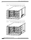
Complete the following steps to reinstall a back card in the MGX 8830 switch:
Step 1 Refer to the notes you made when you recorded the location of each card to ensure that the cards are
installed in the correct slots. For slot assignments for your system, refer to the “MGX 8830 Card
Compartment” section on page 1-48.
Step 2 See the “General Card Installation Guidelines” section on page 3-8 to verify that there are no bent pins,
bent dividers, or damaged connectors on the back cards.
Step 3 Verify that the two extractor levers on the back card are in the latched position (parallel with
the faceplate).
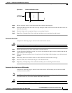
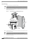
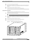
Step 4 Position the back card over the appropriate slot guides and align the back card edge with the slot guides
(left and right) in the chassis.
Step 5 Gently apply even pressure to the sides of the faceplate while pushing the back card into the slot.
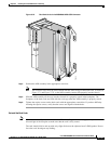
Step 6 Once the back card is installed in the chassis, apply even pressure to the sides of the faceplate to fully
seat the back card.
Step 7 Use the flat-head or Phillips tip of the 3-in-1 tool to tighten the two captive screws on the back
card faceplate.
Note Tighten the left and right captive screws in increments to prevent misalignment of the card. Do
not overtighten the screws, but tighten them enough to secure the card.
Step 8 Repeat Step 2 through Step 7 for each back card that you are reinstalling in the chassis.