


5-112
Cisco MGX 8800/8900 Series Hardware Installation Guide
Releases 2 - 5.2, Part Number OL-4545-01, Rev. H0, May 2006
Chapter 5 Installing the Cisco MGX Switch or Gateway
Installing the MGX 8830 or MGX 8830/B Switch
Caution A rocking motion during connector mating can bend or damage the APS connector pins.
Step 1 Remove one of the back cards connected to the APS assembly
a. Use the flat-head or Phillips tip of the 3-in-1 tool to loosen the two captive screws located on the
left and right of the back card faceplate.
b. Pull each of the two extractor levers, located at the left and right of the faceplate, out to the
horizontal position.
c. Pull evenly on the two extractor levers to remove the back card from the APS connector.
d. Repeat a through c for the remaining back card in the APS connector. The APS connector is still
connected to the second back card when it is removed and comes out of the switch with the card.
Step 2 Carefully separate the second back card from the APS connector by pulling it out with a straight motion.
Step 3 Place the back cards and APS connector in antistatic bags or on an antistatic bench.
Step 4 Repeat through Step 3 for any remaining APS assemblies.
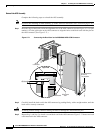
Remove the DC PEM(s)
Complete the following steps to remove a DC PEM from the MGX 8830 switch:
Step 1 Use the flat-head or Phillips tip of the 3-in-1 tool to loosen the two captive screws located on the DC
PEM faceplate.
Step 2 Gently pull the DC PEM out of the switch.
Step 3 Repeat Step 1 and Step 2 for each DC PEM in the switch.
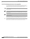
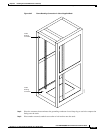
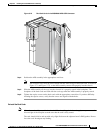
Install the Switch in the Rack or Cabinet
Caution Even with the cards removed, the weight and bulk of the card cage mandate that three or more people
install it. Two installers can support and maneuver the MGX 8830 switch while a third secures it to
the rack or cabinet.
This section details the procedures necessary for installing the MGX 8830 switch with a mechanical lift
in a 19-inch or 23-inch rack or a 19-inch cabinet.
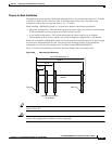
• “Install the Switch in a 19-Inch or 23-Inch Rack” section on page 5-119
• “Install the Switch in a 19-Inch Cabinet” section on page 5-121
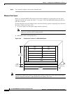
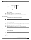
Tip If the screw holes on the card cage are not aligned with the holes on the frame, place a flat-blade
screwdriver under the card cage to raise it. Insert the screws and tighten them. Remove the screwdriver
from beneath the card cage.