


1-55
Cisco MGX 8800/8900 Series Hardware Installation Guide
Releases 2 - 5.2, Part Number OL-4545-01, Rev. H0, May 2006
Chapter 1 Product Overviews
Cisco MGX 8830 or MGX 8830/B Switch
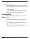
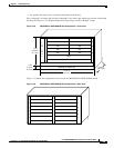
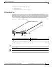
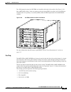
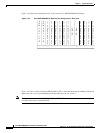
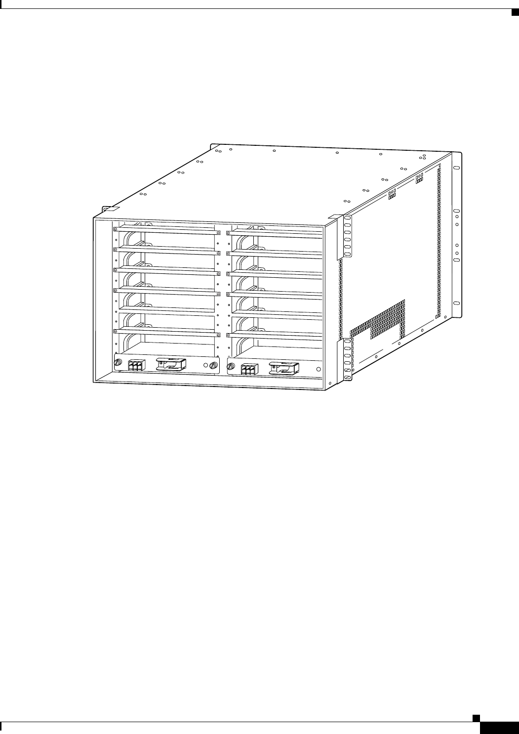
For a DC-powered system, the DC PEMs are installed at the back of the switch. (See Figure 1-40.)
On an MGX 8830 switch, it does not matter on which side the PEM is installed, and if two PEMs are
installed, there is no primary or secondary PEM, unlike the PEM requirements for the MGX 8850
switches.
Figure 1-40 DC PEMs Installed in Back of the Switch
For more information about DC power requirements, see the “Power Requirements” section on
page 3-17.
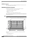
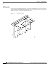
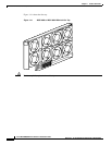
Fan Tray
The MGX 8830 or MGX 8830/B has a fan tray located on the left side of the switch (when it is viewed
from the front). The fan tray pulls ambient cooling air into the system through openings between the
front card faceplates, over the boards in the switch, and out through the air exhaust openings on the left
side of the switch.
The fan tray houses eight fans that provide system cooling. The MGX 8830 or MGX 8830/B switch
requires that a fan tray be installed when the system is in operation. Figure 1-34 shows the location of
the fan tray in a MGX 8830 or MGX 8830/B switch.
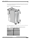
The cooling system incorporates the following design features:
• –48 VDC fans with rotation sensing
• N+1 fan redundancy
• Hot swappable
• Noise level < 65 dBA
23827
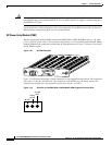
48 VDC
30A
TB1
1
2
3
OFF
48 VDC
30A
TB1
1
2
3
OFF