


2-61
Cisco MGX 8800/8900 Series Hardware Installation Guide
Releases 2 - 5.2, Part Number OL-4545-01, Rev. H0, May 2006
Chapter 2 Illustrated Card List for MGX Switches and the MGX 8880 Media Gateway
Front Cards
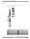
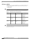
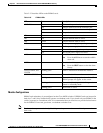
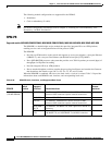
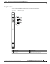
Table 2-25 describes LEDs on the PXM45 cards.
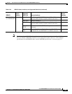
Module Configurations
PXM45 card redundancy is preconfigured on the Cisco MGX switches. If PXM45 cards are inserted in
both slots 7 and 8, they automatically operate as redundant cards. If you install only one PXM45 in the
switch, it operates as a standalone card. It is recommended that you install two to provide fault tolerance
for the PXM45. If one card goes down, a redundant card takes over.
Note For the cards to operate redundantly, Y-cabling must be present on the external clock ports on the
back cards.
Table 2-25 PXM45 LEDs
LED Status Description
CNTLR Port Green The controller port is active.
Red A major alarm exists on the controller port.
Yellow A minor alarm exists on the controller port.
Off The port is inactive.
CR Blue A critical network alarm is active.
MJ Red A major network alarm is active.
MN Yellow A minor network alarm is active.
DC-A Green The first power supply is operating correctly.
Red The first power supply has failed.
DC-B Green The second power supply is operating correctly.
Red The second power supply has failed.
ACO Yellow An audible alarm is on.
Note Press the ACO button to turn the audible
alarm off.
HIST Green There is alarm history on the card.
Note Press the HIST button to clear the alarm
history.
ENET, ENETA, and
ENETB
Flashing green Traffic is detected on the Ethernet interface.
SYSTEM STATUS Red The module is in Reset mode.
Blinking red The module is booting up from boot flash. The
PXM45 prompt will appear on the screen.
Blinking yellow The module is booting and initializing or the
module is in Standby mode.
Blinking green The module is active.