


1-54
Cisco MGX 8800/8900 Series Hardware Installation Guide
Releases 2 - 5.2, Part Number OL-4545-01, Rev. H0, May 2006
Chapter 1 Product Overviews
Cisco MGX 8830 or MGX 8830/B Switch
Caution Although the PXM1E-4-155 does not need an APS connector to support APS line redundancy, it is
recommended that you install the PXM1E-4-155 in an APS connector to support a seamless upgrade to
the PXM1E-8-155 card.
For information on APS configuration, refer to the appropriate Cisco MGX release notes, or the Cisco
MGX software configuration guide for your software release.
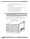
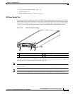
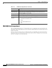
DC Power Entry Module (PEM)
The DC Power Entry Module (PEM) connects the MGX 8830 or MGX 8830/B switch to a –48 VDC
(–42 to –56 VDC) power source. You can install one (primary) or two (secondary/redundant) DC PEMs.
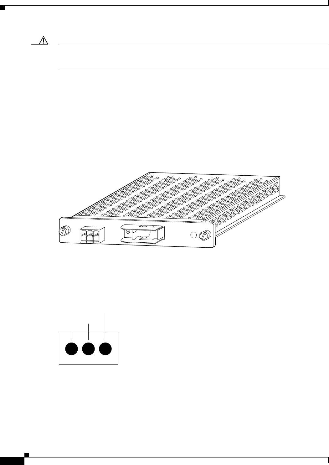
Each DC PEM must be connected to a dedicated 30 A regulated source. Figure 1-38 shows a close-up of
the DC PEM faceplate.
Figure 1-38 DC PEM Faceplate
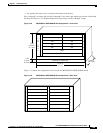
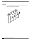
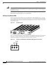
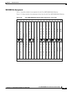
Figure 1-39 illustrates the polarity of each connection on the pluggable terminal block. The connection
at the left (1) is for the –48 VDC wire. The connection in the middle (2) is the safety ground. The
connection at the right (3) is for the positive return wire (for the –48 VDC).
Figure 1-39 Polarities at the MGX 8830 or MGX 8830/B PEM Pluggable Terminal Block
48 VDC
30A
TB1
1
2
3
OFF
17275
26265
123
-48 VDC
-48 VDC
return
Safety
ground