


5-36
Cisco MGX 8800/8900 Series Hardware Installation Guide
Releases 2 - 5.2, Part Number OL-4545-01, Rev. H0, May 2006
Chapter 5 Installing the Cisco MGX Switch or Gateway
Installing the MGX 8850 (PXM1E/PXM45) Switch, MGX 8850/B or MGX 8880 Media Gateway
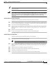
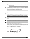
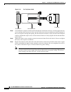
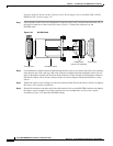
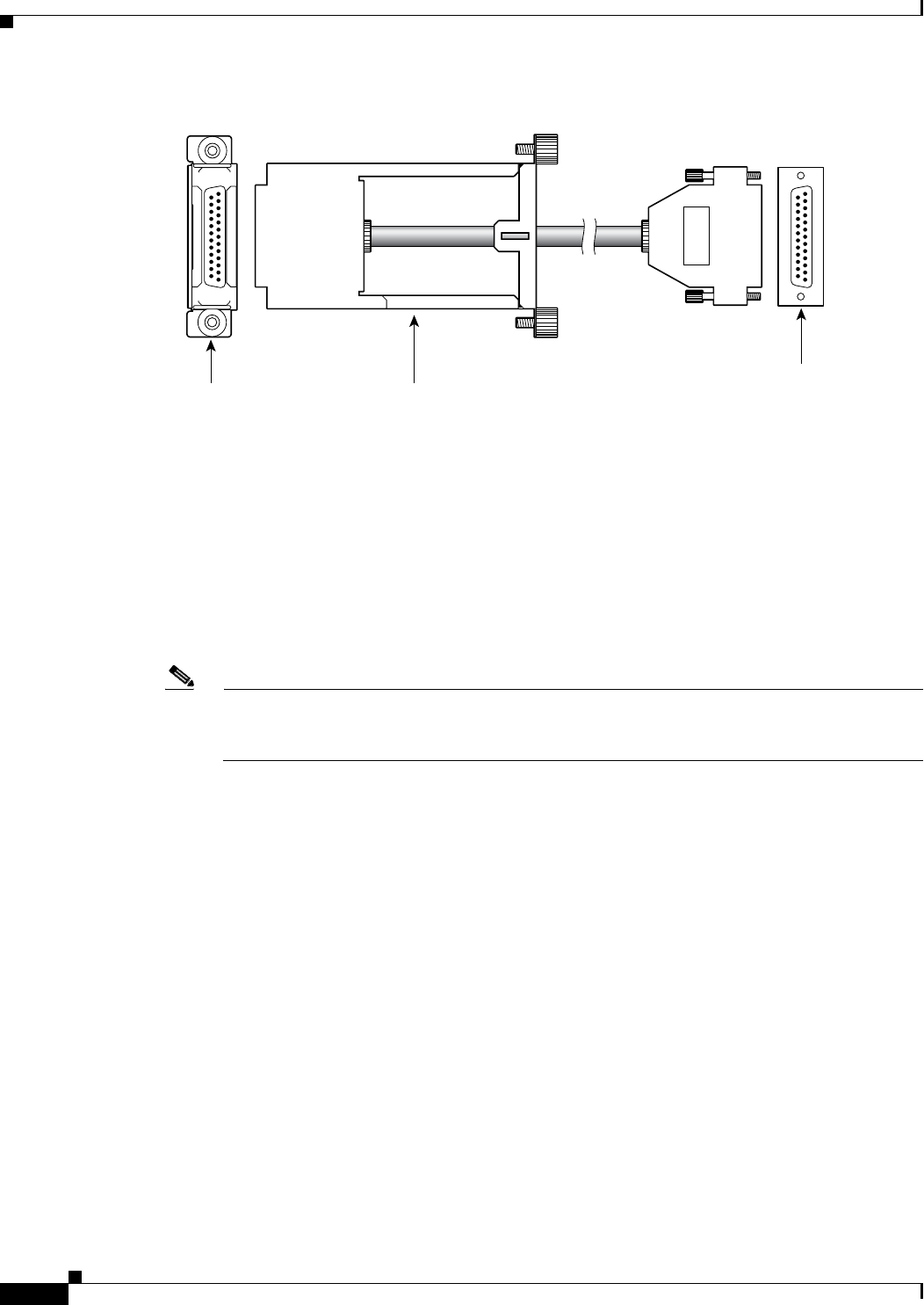
Figure 5-19 Fan Tray Power Cable
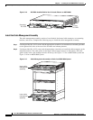
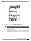
Step 2
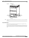
Use both hands to slip the connector frame through the second (lower fan tray) or fourth (upper fan tray)
access opening at the bottom rear of the card cage. Move the connector straight toward the backplane so
that you can guide it through the opening. Be sure that the D-connector is fully inserted in the backplane
connector and that the captive screws on the connector frame are clearly aligned with the threaded holes
on the chassis.
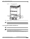
Step 3 Tighten the captive screws enough to secure the connector frame flush to the chassis. Do not overtighten
the screws or use a power screwdriver.
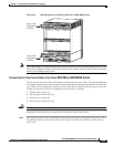
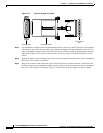
Step 4 Plug the D-connector at the other end of the cable into the connector on the back of the lower or upper
fan tray and tighten the captive screws enough to secure the connector. Do not overtighten the screws or
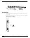
use a power screwdriver. Figure 5-20 shows the fan tray power cabling.
Note The bottom of the illustration in Figure 5-20 shows the back of an AC power supply tray. The
presence of the AC power supply tray will not affect the fan tray power cabling. The fan tray
power cabling is the same for an AC- or DC-powered system.
17674
Connector frameTo backplane
To fan tray