


5-25
Cisco MGX 8800/8900 Series Hardware Installation Guide
Releases 2 - 5.2, Part Number OL-4545-01, Rev. H0, May 2006
Chapter 5 Installing the Cisco MGX Switch or Gateway
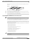
Installing the MGX 8850 (PXM1E/PXM45) Switch, MGX 8850/B or MGX 8880 Media Gateway
Warning
Never attempt to lift the chassis with the handles on the power supplies, fan trays, or the switching
modules. These handles are not designed to support the weight of the chassis. Using them to lift or
support the chassis can result in severe damage to the equipment and serious bodily injury.
Statement 50
Warning
Two people are required to lift the chassis. Grasp the chassis underneath the lower edge and lift with
both hands. To prevent injury, keep your back straight and lift with your legs, not your back. To prevent
damage to the chassis and components, never attempt to lift the chassis with the handles on the
power supplies or on the interface modules. These handles were not designed to support the weight
of the chassis.
Statement 5
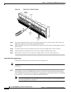
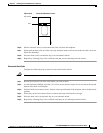
Install the Switch in a 19-Inch or 23-Inch Rack
Complete the following steps to install the switch in a 19-inch or 23-inch rack:
Step 1 Attach one mid-mounting bracket to each side of the Cisco MGX 8850 switch before installing the unit
in a rack. You need a mounting kit to accommodate a 23-inch rack (Cisco Part Number MGX-MNT23).
Step 2 Have two people move the switch to the desired position in the rack, or, if spacers are used, slide the
switch across the spacers and position it in the rack.
Note Maintain a gap of about 0.060 inch (1/16 inch) between units. Use a spacer if necessary.
Step 3 Use the 10-32 truss head screws to secure the switch to the mid-mounting rails.
Install the Switch in a 19-Inch Cabinet
Complete the following steps to install the switch in a 19-inch cabinet:
Step 1 Have two people move the switch to the desired position in the rack, or, if spacers are used, slide the
switch across the spacers and position it in the rack.
Note The rear-mounting brackets cannot be installed before you put the unit in a 19-inch cabinet.
Maintain a gap of about 0.060 inch (1/16 inch) between units. Use a spacer if necessary.
Step 2 Use the 10-32 truss head screws to secure the switch to the front-mounting rails.
Step 3 Attach the rear-mounting brackets to the rack.
Step 4 Use the 10-32 truss head screws to secure the switch to the rear-mounting brackets.