


5-95
Cisco MGX 8800/8900 Series Hardware Installation Guide
Releases 2 - 5.2, Part Number OL-4545-01, Rev. H0, May 2006
Chapter 5 Installing the Cisco MGX Switch or Gateway
Installing the MGX 8950 Switch
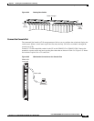
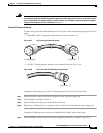
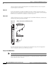
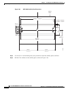
Step 11 Attach the end of the wire (from Step 10) with the ring or space lug to the –48 VDC, as shown in
Figure 5-62.
Step 12 Attach the other end of the wire from Step 10 to the DC source
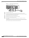
Step 13 Use a Phillips-head screwdriver and two screws to attach the plastic cover over the terminal block on the
DC PEM.
Step 14 Turn on the power source and turn the DC PEM power switch on
Step 15 Verify that the fans are running by listening or feeling for air movement. The following LEDs should
be lit:
• AC and DC LEDs on each power supply should be green.
• DC OK LED on each DC PEM should be green.
• Status LED on the PXM45 should be green.
• Standby LED on each service module should be yellow.
Connect the External Clock
This step is optional. For information, see “Connect the External Clock” section on page B-7.
Connect the Alarms
Note This step is optional.
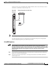
Dry contact relay closures are available for forwarding MGX 8950 switch alarms to an alarm system.
Separate visual and audible alarm outputs are available for critical, major, and minor alarm outputs, and
the outputs are provided through the use of a DB-15 connector on the PXM user interface back card
(PXM-UI-S3 and PXM-UI-S3/B).
Complete the following steps to connect the external clock:
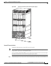
Step 1 Verify that you have a PXM-UI-S3 or PXM-UI-S3/B back card installed in slots 7 and 8 in the upper rear
bay of the switch.
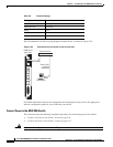
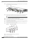
Step 2 Connect the DB-15 cable to the ALARM port on the PXM-UI-S3 or PXM-UI-S3/B back card.
Note See Appendix B, “Cable Specifications” for cable requirements.
Step 3 Connect the other end of the cable to the alarm source.
Connect the MP Connection
Note This step is optional.