


C-7
Cisco MGX 8800/8900 Series Hardware Installation Guide
Releases 2 - 5.2, Part Number OL-4545-01, Rev. H0, May 2006
Appendix
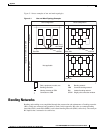
Bonding Networks
Equipment backplane speeds are in the category above 800 MHz. Because the design must anticipate the
worst case scenario, concerns about RF damage are much greater. At 800 MHz only 10 inches of wire
represents 500 ohms reactance.
For the average coaxial cable shield integrity to be maintained, the termination of the shield must see a
ground reference of no more than 50 ohms. The importance of this relationship is that although the 800
MHz speed is not the data speed of E1/T1, it must mitigate frequency susceptibility issues that will upset
the 800 MHz operation.
Therefore, the multipoint grounding techniques must be used as supported by the K.27
recommendations. Although K.27 is designed around lightning and transient issues, the same theory
applies to the higher frequency problems; they are just smaller in scale. As frequency increases, the wave
length becomes smaller, and the reactance of a fixed length of wire goes up.
The need is to multipoint ground our backplane and the 48 VDC return directly to the frame at frequent
intervals that represent at least 1/20 of a wavelength. The frame, in turn, will be bonded to the isolated
mesh-bonding mat. At 800 MHz, 18.8 mm represent a 20th of a wavelength, so grounding/bonding must
be done at these intervals to maintain backplane-to-cabinet integrity for its full perimeter. Using
capacitors to achieve the necessary bonding becomes extremely difficult at these frequencies in addition
to the added cost due to the isolation breakdown voltage requirements of 2.1 kilovolts, should the old
philosophy be insisted upon.
The theoretical concepts are confirmed by practical experience and lead to the general principles listed
below. A consequence of applying these principles is that the number of conductors and interconnections
in the CBN is increased until adequate shielding is achieved. Concerning the important issue of electric
shock, the following implementation principles apply to mitigation of electric shock as well as to
equipment malfunction:
1. All elements of the CBN shall be interconnected. Multiple interconnections, resulting in a
three-dimensional mesh, are especially desirable. Increasing the number of CBN conductors and
their interconnections increases the CBN shielding capability and extends the upper frequency limit
of this capability.
2. It is desirable for the egress points for all conductors leaving the building (including the earthing
conductor) to be located close together. In particular, the AC power entrance facilities,
telecommunications cable entrance facilities, and the earthing conductor entry point should be close
together.
3. The facility should have a main earthing terminal located as close as possible to the entrance to the
AC power and telecommunications cable entrance facilities. The main earthing terminal shall
connect to the following:
• Earthing electrode(s) via a conductor of shortest length
• One or more earthing electrodes
• Neutral conductor of the AC power feed (in TN systems)
• Cable shields (at the cable entrance) either directly or via arresters or capacitors if required by
corrosion considerations
4. The CBN shall be connected to the main earthing terminal. Multiple conductors between the CBN
and the main earthing terminal are recommended.
5. As contributors to the shielding capability of the CBN, interconnection of the following items of the
CBN is important:
• Metallic structural parts of the building including I-beams and concrete reinforcement where
accessible
• Cable supports, trays, racks, raceways, and AC power conduit