


5-129
Cisco MGX 8800/8900 Series Hardware Installation Guide
Releases 2 - 5.2, Part Number OL-4545-01, Rev. H0, May 2006
Chapter 5 Installing the Cisco MGX Switch or Gateway
Installing the MGX 8830 or MGX 8830/B Switch
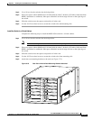
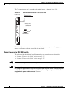
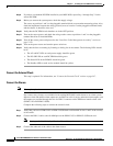
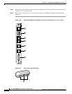
Figure 5-82 Polarities at the MGX 8830 PEM Pluggable Terminal Block
Step 4
Locate the wiring block for TB1.
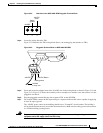
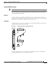
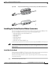
Figure 5-83 illustrates the TB1 wiring block (that is, the mating plug that attaches to TB1).
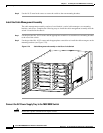
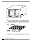
Figure 5-83 Pluggable Terminal Block on MGX 8830 DC PEM
Step 5
Insert and secure the stripped ends of the 10 AWG wire in the wiring block as shown in Figure 5-82 and
Figure 5-83. Figure 5-83 shows the assembly with an example wire and the screw that secures it in the
pluggable wire block.
Step 6 Plug the pluggable terminal block to the receptacle TB1 on the DC PEM.
Step 7 For each DC PEM, connect the DC input wiring to a separate dedicated DC source capable of supplying
at least 30 amps (typical).
The –48VDC power source in the building should have a 30 Amp DC circuit breaker. The building’s
wiring should include an easily accessible disconnect device. Make sure the safety ground wire connects
to a reliable building (earth) ground.
Warning
For personnel safety, the green or green/yellow wire must connect to safety (earth) ground at both the
equipment and at the supply side of the DC wiring.
26265
123
-48 VDC
-48 VDC
return
Safety
ground
10 AWG
or 4 sq. mm.
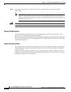
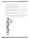
–48 VDC Return
Safety ground
–48 VDC
3
2
1
26264