


5-74
Cisco MGX 8800/8900 Series Hardware Installation Guide
Releases 2 - 5.2, Part Number OL-4545-01, Rev. H0, May 2006
Chapter 5 Installing the Cisco MGX Switch or Gateway
Installing the MGX 8950 Switch
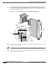
Note Some cards have an “insertion delay latch” that needs to be raised before closing the extractor
lever.
Step 8 Repeat Step 2 through Step 7 for each front card that you are reinstalling in the chassis.
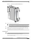
Step 9 Install blank faceplates in any empty slot, as necessary.
Step 10 Close the front door on the switch, as necessary.
Install the MGX 8950 Switch with a Mechanical Lift
Note If you installed the switch using instructions in the previous section, proceed to the “Install the Upper
Fan Tray” section on page 5-76.
The MGX 8950 switch is shipped with all of the ordered cards and modules installed and tested at the
factory.
It is recommended that you install the MGX 8950 switch using a mechanical lift. This switch can be
installed easily by a single person if a mechanical lift is used. If a mechanical lift is not available, the
cards and modules must be removed so the switch can be lifted into the rack. If you are not installing the
MGX 8950 switch using a mechanical lift, go to the “Install the MGX 8950 Switch without a Mechanical
Lift” section on page 5-65.
When using a mechanical lift, keep the following guidelines in mind:
• The lift should be capable of handling 300 lb.
• The T & S Hefti-Lift, Model HYD-5 is a good example of the type of lift you should use. For
specifications, see http://www.tseq.com/products/ergosol/hefti-lift.htm.
• Minimum platform dimensions are 17.5 inches wide by 24 inches deep.
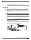
This section details the procedures you should use to install the MGX 8950 switch with a mechanical
lift in a 19-inch or 23-inch rack or a 19-inch cabinet.
• “Install the Switch in a 19-Inch or 23-Inch Rack” section on page 5-75
• “Install the Switch in a 19-Inch Cabinet” section on page 5-75
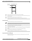
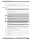
Tip If the screw holes on the card cage are not aligned with the holes on the frame, place a flat-blade
screwdriver between the card cage and fan tray to raise the card cage. Insert the screws and tighten them,
and then remove the screwdriver from between the fan tray and card cage.
Tip If a component requires more than two screws for installation in the rack or cabinet, install the two
bottom screws first.