


5-18
Cisco MGX 8800/8900 Series Hardware Installation Guide
Releases 2 - 5.2, Part Number OL-4545-01, Rev. H0, May 2006
Chapter 5 Installing the Cisco MGX Switch or Gateway
Installing the MGX 8850 (PXM1E/PXM45) Switch, MGX 8850/B or MGX 8880 Media Gateway
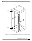
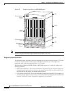
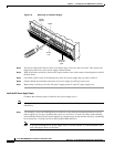
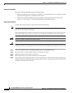
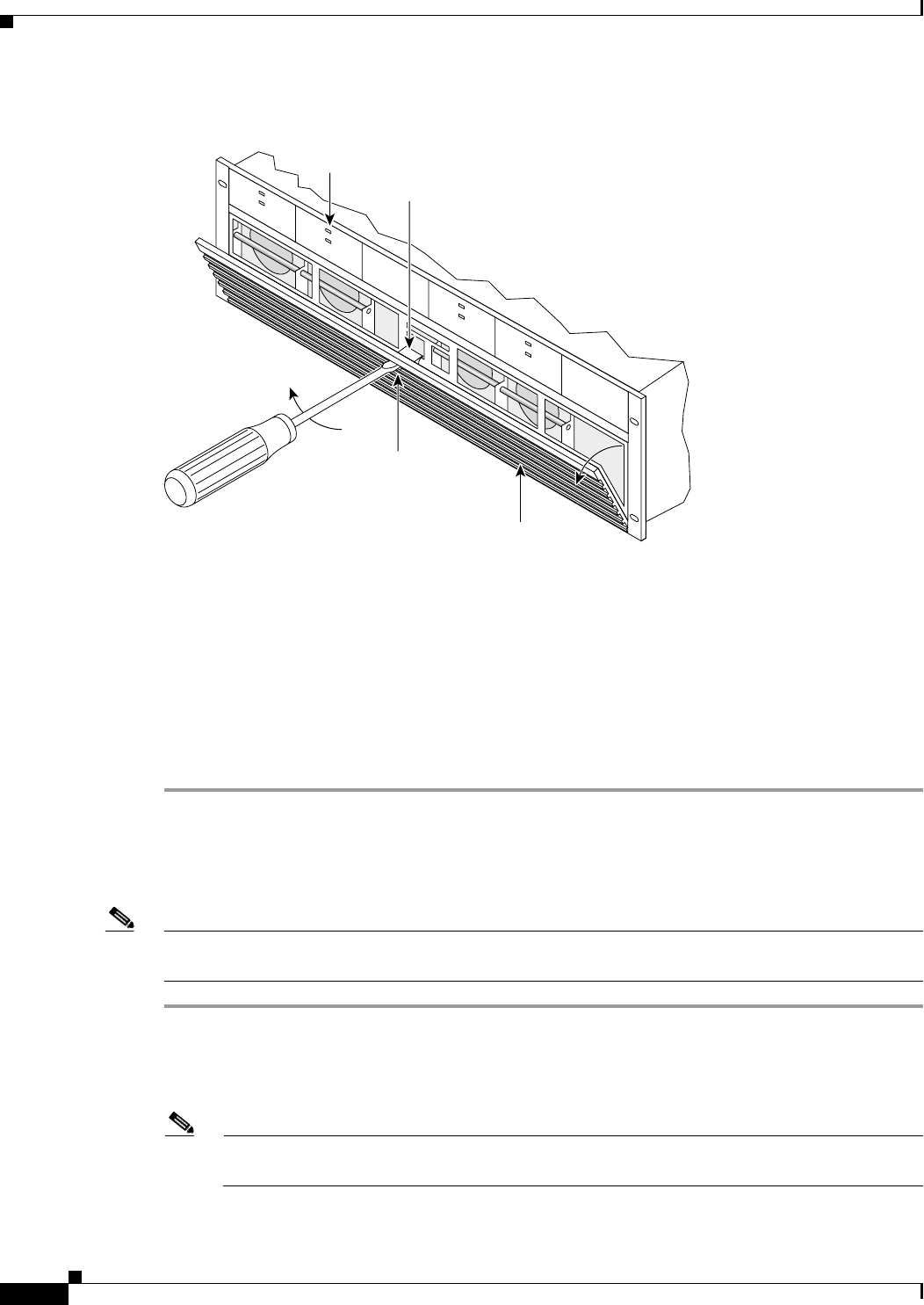
Figure 5-9 Removing an AC Power Supply
Step 3
Tilt the air intake grille down to about a 45-degree angle, lift it out, and set it aside. This exposes the
hinged door that serves as the power supply retainer bracket.
Step 4 With a flat-blade screwdriver, unscrew the captive retainer screw in the center of the hinged door and tilt
the door down.
Step 5 Loosen the captive screw at the bottom front of the AC power supply that you want to remove.
Step 6 Grip the handle and carefully remove the AC power supply by pulling it toward you.
Step 7 Repeat Step 5 and Step 6 for each AC power supply present in each AC power supply tray.
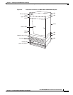
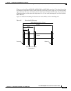
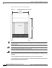
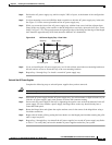
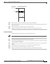
Install the AC Power Supply Tray(s)
Complete the following steps to install the AC power supply tray(s).
Note For optimum performance, it is recommended that you install dual AC power systems for full
redundancy.
Step 1 Use mounting screws and a Phillips-head screwdriver to attach the mid-mounting brackets to the AC
power supply tray if you are installing the system in a 19-inch or 23-inch rack. Insert each mounting
screw from the inside of the AC power supply tray so that the nut is on the outside of the tray. A mounting
kit is needed for a 23-inch rack (Cisco Part Number MGX-MNT23).
Note If you are installing the AC power supply tray in a 19-inch cabinet, it is front-mounted in the
rack with support from rear brackets.
44142
A
C
D
C
1200W
A
C
D
C
1200W
A
C
D
C
1200W
A
C
D
C
1200W
Released
air intake
grille
Access
hole
Latch
Power
supply