


5-3
Cisco MGX 8800/8900 Series Hardware Installation Guide
Releases 2 - 5.2, Part Number OL-4545-01, Rev. H0, May 2006
Chapter 5 Installing the Cisco MGX Switch or Gateway
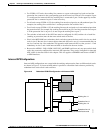
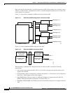
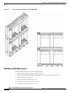
Installing the MGX 8850 (PXM1E/PXM45) Switch, MGX 8850/B or MGX 8880 Media Gateway
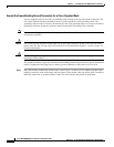
Note Using a lift to install a fully loaded MGX 8850, MGX 8850/B, or MGX 8880 system in a rack greatly
simplifies the installation process, because the modules do not need to be removed from the chassis.
Before proceeding with the installation, verify that all of the ordered parts are present and in good
condition. Store a record of the parts and serial numbers. If any parts are missing or damaged, contact
your sales representative.
Caution Proper ESD protection is required whenever you handle Cisco equipment. Installation and maintenance
personnel should be properly grounded through the use of grounding straps to eliminate the risk of ESD
damage to the equipment. Modules are subject to ESD damage whenever they are removed from
the chassis.
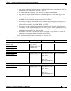
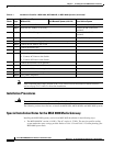
Table 5-1 Installation Checklist—MGX 8850, MGX 8850/B, or MGX 8880 Systems
Check Steps
Rack-Mounted System
(Without Lift) Rack-Mounted System (with Lift) Cisco Cabinet System
Step 1
Install stability plate for seismic anchoring
Step 2
Ground the frame bonding ground connection for a Cisco-supplied rack
Step 3
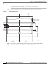
Measure Rack Space Connect the Fan tray power cables
to the switch
Step 4
Prepare for rack installation Connect the AC power supply tray
to the switch
Step 5
Install the AC Power Supply Tray, as necessary
• Remove the AC power supplies from the AC power supply tray
• Install the AC Power Supply Tray(s)
• Reinstall the AC Power Supplies
Connect the DC PEM to the switch
Step 6
Install the Air Intake Plenum Connect the Back Cards.
Step 7
Install the Lower Fan Tray Connect the Console Port.
Step 8
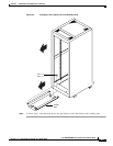
Install the switch without a
Mechanical Lift
• Prepare for Installation
• Remove the Front Cards
• Remove the Back Cards
• Remove the Back Cards from
an APS Assembly
• Install the Switch in the Rack
• Reinstall the APS Assembly
• Reinstall the Back Cards
• Reinstall the Front Cards
Install the switch with a
Mechanical Lift
• Install the Switch in a 19-Inch
or 23-Inch Rack
• Install the Switch in a 19-Inch
Cabinet
Connect Power to the switch
• Connect AC Power to the
Switch
• Connect DC Power to the
Switch
Step 9
Install the Upper Fan Tray Connect the External Clock
(optional)