


3-14
Cisco MGX 8800/8900 Series Hardware Installation Guide
Releases 2 - 5.2, Part Number OL-4545-01, Rev. H0, May 2006
Chapter 3 Preparing for Installation
Site Requirements for the MGX 8850 or MGX 8850/B Switch
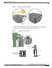
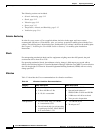
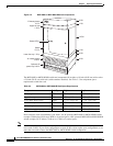
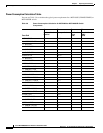
Figure 3-3 MGX 8850 or MGX 8850/B Switch Components
The MGX 8850 or MGX 8850/B switch and components fit in either a 19-inch (48.26 cm) wide rack or
a 23-inch (58.42 cm) wide rack (with extenders installed). See Table 3-3 for component space
requirements within the rack.
Plan so that the rack accommodates your needs. An AC-powered MGX 8850 or MGX 8850/B switch
occupies 35.00 inches (88.9 cm or 20 RUs) of vertical space. A DC-powered MGX 8850 or MGX 8850/B
switch occupies 29.75 inches (75.69 cm or 17 RUs) of vertical space.
Note In a central office (CO) and private enterprise (PE) environment, the total amount of rack space should
not exceed 42 RUs. If your total configuration exceeds 42 RUs, either replan your configuration or use
more than one rack to house the MGX 8850 or MGX 8850/B switch components.
17670
2 RU
1 RU
10 RU
1 RU
3 RU
3 RU
Exhaust plenum
3.5 in.
Upper fan tray
1.75 in.
Lower fan tray 1.75 in.
Switch
17.5 in.
Air intake plenum
5.25 in.
Optional AC
power tray 5.25 in.
Status LEDs
A
C
D
C
1
2
0
0
W
AC
DC
1
2
0
0
W
AC
D
C
1200W
A
C
D
C
1200W
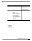
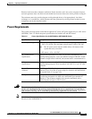
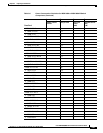
Table 3-3 MGX 8850 or MGX 8850/B Rack Space Requirements
Component Rack Space Height Depth
Exhaust plenum 2 RUs 3.50 in. (8.89 cm) 21.5 in. (54.61 cm)
Upper fan tray 1 RU 1.75 in. (4.45 cm) 21.5 in. (54.61 cm)
Cisco MGX 8850 switch 10 RUs 17.5 in. (44.45 cm) 21.5 in. (54.61 cm)
Lower fan tray 1 RU 1.75 in. (4.45 cm) 21.5 in. (54.61 cm)
Air intake plenum 3 RUs 5.25 in. (13.34 cm) 21.5 in. (54.61 cm)
AC power supply tray (optional) 3 RUs 5.25 in. (13.34 cm) 21.5 in. (54.61 cm)