


Chapter 4 Parameters|
Revision Nov. 2008, VLE1, SW V1.03 4-47
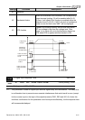
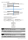
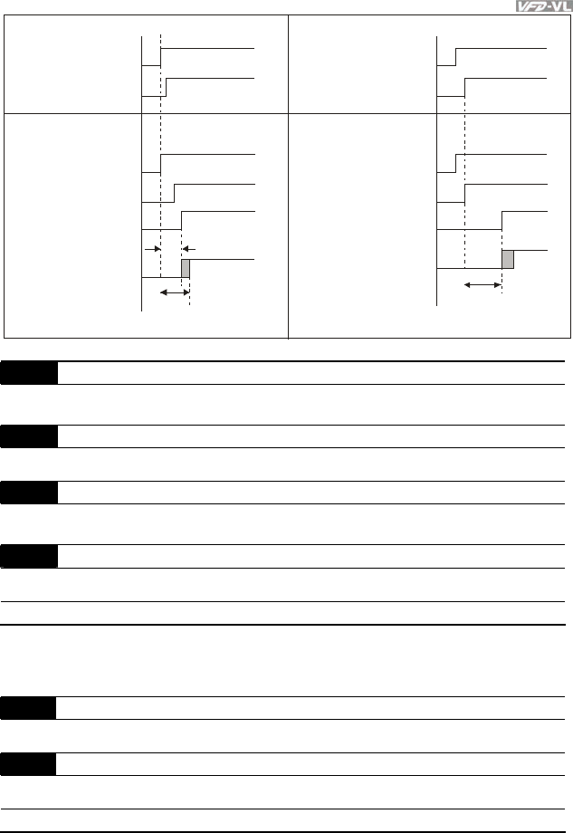
Enable
FWD/REV
Enable
FWD/REV
02-31
C
o
n
t
r
o
l
l
e
r
S
i
g
n
a
l
o
u
t
p
u
t
D
r
i
v
e
r
M
u
l
t
i
f
u
n
c
t
i
o
n
o
u
t
p
u
t
/
i
n
p
u
t
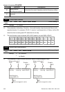
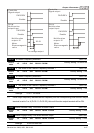
Multifunction
output=15
Motor
Electromagnetic
valve
02-31
no voltage output
C
o
n
t
r
o
l
l
e
r
S
i
g
n
a
l
o
u
t
p
u
t
Enable
FWD/REV
D
r
i
v
e
r
M
u
l
t
i
f
u
n
c
t
i
o
n
o
u
t
p
u
t
/
i
n
p
u
t
Enable
FWD/REV
Multifunction
output=15
Motor
Electromagnetic
valve
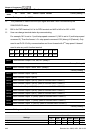
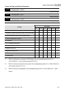
02-25 Desired Frequency Attained 1 Unit: 0.01
Control
mode
VF VFPG SVC FOCPG FOCPM
Factory setting: 60.00/50.00
02-26 The Width of the Desired Frequency Attained 1 Unit: 0.01
Control
mode
VF VFPG SVC FOCPG FOCPM
Factory setting: 2.00
02-27 Desired Frequency Attained 2 Unit: 0.01
Control
mode
VF VFPG SVC FOCPG FOCPM
Factory setting: 60.00/50.00
02-28 The Width of the Desired Frequency Attained 2 Unit: 0.01
Control
mode
VF VFPG SVC FOCPG FOCPM
Factory setting: 2.00
Settings 0.00 ~ 120.00Hz
Once output frequency reaches desired frequency and the corresponding multi-function output
terminal is set to 3 or 4 (Pr.02-11~Pr.02-22), this multi-function output terminal will be ON.
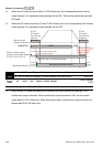
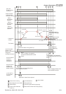
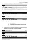
02-29 Brake Release Delay Time when Elevator Starts Unit:0.001
Control
mode
VF VFPG SVC FOCPG TQCPG FOCPM
Factory setting: 0.250
02-30 Brake Engage Delay Time when Elevator Stops Unit:0.001
Control
mode
VF VFPG SVC FOCPG TQCPG FOCPM
Factory setting: 0.250
Settings 0.000~65.000 Sec