


Chapter 2 Installation and Wiring|
Revision Nov. 2008, VLE1, SW V1.03 2-11
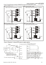
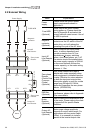
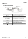
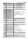
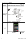
Terminal symbols and functions
Terminal
Symbol
Terminal Function
Factory Settings (SINK)
ON: Connect to DCM
FWD Forward-Stop Command
ON: RUN in FWD direction
OFF: Stop acc. to Stop Method
REV Reverse-Stop Command
ON: RUN in REV direction
OFF: Stop acc. to Stop Method
MI1 Multi-function Input 1
MI2 Multi-function Input 2
MI3 Multi-function Input 3
MI4 Multi-function Input 4
MI5 Multi-function Input 5
MI6 Multi-function Input 6
MI7 Multi-function Input 7
MI8 Multi-function Input 8
Refer to Pr.02-01 to Pr.02-08 for programming
the Multi-function Inputs.
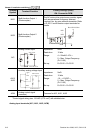
ON: input voltage is 24Vdc (Max. 30Vdc), input
impedance is 3.75k
OFF: leakage current tolerance is 10A.
MI8: when JP1 is inserted, this function is
disabled.
COM Digital Signal Common
Common for digital inputs and used for SINK
mode
+E24V
Digital Signal Common
(Source)
+24V 80mA
DCM Digital Signal Common (Sink)
Common for digital inputs and used for SINK
mode
RA
Multi-function Relay Output 1
(N.O.) a
RB
Multi-function Relay Output 1
(N.C.) b
RC Multi-function Relay Common
MRA
Multi-function Relay Output 2
(N.O.) a
MRC Multi-function Relay Common
Resistive Load:
5A(N.O.)/3A(N.C.) 240VAC
5A(N.O.)/3A(N.C.) 24VDC
Inductive Load:
1.5A(N.O.)/0.5A(N.C.) 240VAC
1.5A(N.O.)/0.5A(N.C.) 24VDC
To output monitor signal, including in operation,
frequency arrival, overload and etc.
Refer to Pr.02-11~02-12 for programming
+10V
-10V
Potentiometer Power Supply -10~+10VDC 20mA (variable resistor 3-5kohm)
MCM
Multi-function Output
Common (Photocoupler)
Max. 48VDC 50mA