


Chapter 4 Parameters|
4-42 Revision Nov. 2008, VLE1, SW V1.03
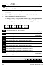
02-10 Digital Input Operation Direction Unit: 1
Control
mode
VF VFPG SVC FOCPG TQCPG FOCPM
Factory setting: 0
Settings 0 ~ 65535
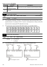
This parameter is used to set the input signal level and it won’t be affected by the
SINK/SOURCE status.
Bit0 is for FWD terminal, bit1 is for REV terminal and bit2 to bit9 is for MI1 to MI8.
User can change terminal status by communicating.
For example, MI1 is set to 1 (multi-step speed command 1), MI2 is set to 2 (multi-step speed
command 2). Then the forward + 2
nd
step speed command=1001(binary)=9 (Decimal). Only
need to set Pr.02-10=9 by communication and it can forward with 2
nd
step speed. It doesn’t
need to wire any multi-function terminal.
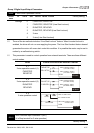
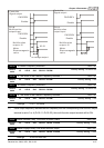
bit9 bit8 bit7 bit6 bit5 bit4 bit3 bit2 bit1 bit0
MI8 MI7 MI6 MI5 MI4 MI3 MI2 MI1 REV FWD
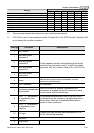
02-11 Multi-function Output 1 RA, RB, RC (Relay1)
Factory Setting: 11
02-12 Multi-function Output 2 MRA, MRC (Relay2)
Factory Setting: 1
02-13 Multi-function Output 3 (MO1)
02-14 Multi-function Output 4 (MO2)
02-15 Multi-function Output 5 (MO3) (need to use with EMVL-IODA01)
02-16 Multi-function Output 6 (MO4) (need to use with EMVL-IODA01)
02-17 Multi-function Output 7 (MO5) (need to use with EMVL-IODA01)
02-18 Multi-function Output 8 (MO6) (need to use with EMVL-IODA01)
02-19 Multi-function Output 9 (MO7) (need to use with EMVL-IODA01)
02-20 Multi-function Output 10 (MO8) (need to use with EMVL-IODA01)
02-21 Multi-function Output 11 (MO9) (need to use with EMVL-IODA01)
02-22 Multi-function Output 12 (MO10) (need to use with EMVL-IODA01)
Factory Setting: 0
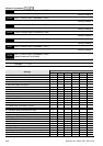
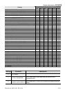
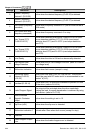
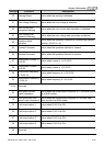
Settings 0-41
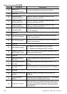
Control Mode
Settings
VF VFPG SVC FOCPG TQCPG FOCPM
0: No function
○ ○ ○ ○ ○ ○
1: Operation indication
○ ○ ○ ○ ○ ○