


Appendix B Accessories|
Revision Nov. 2008, VLE1, SW V1.03 B-29
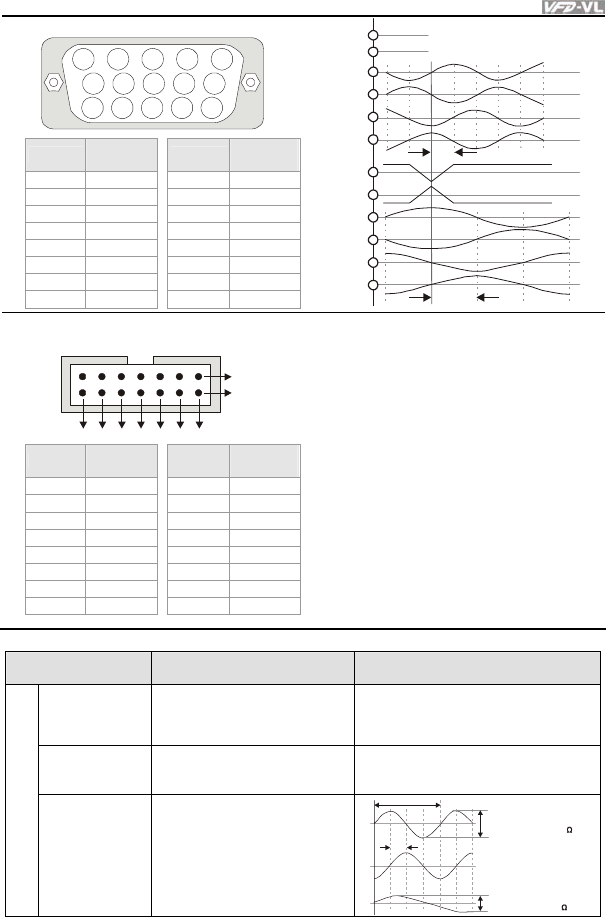
VFD-VL series
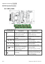
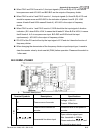
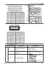
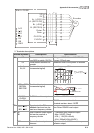
5 4 3 2 1
10 9 8 7 6
15 14 13 12 11
Pin NO
Terminal
Name
Pin NO
Terminal
Name
1 B- 9 +5V
2 NC 10 SIN
3 Z+ 11 SIN’
4 Z- 12 COS
5 A+ 13 COS’
6 A- 14 NC
7 0V 15 NC
8 B+
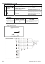
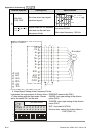
A+
A-
Z+
Z-
B+
B-
SIN
SIN'
COS
COS'
+5V
0V
Vdc
GND
90 el.
0
90 mech.
0
Heidenhain ERN1387
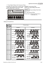
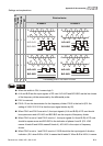
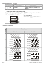
123456
B
A
7
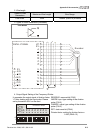
Pin NO
Terminal
Name
Pin NO
Terminal
Name
5a B- 1b UP
NC NC 1a C-
4b R+ 7b C+
4a R- 2b D+
6a A+ 6a D-
2a A- - -
5b 0V - -
3b B+
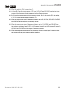
2. Terminals descriptions
Terminal Symbols Descriptions Specifications
+5V
Specific power output of
encoder
Voltage: +5V±0.5V
Current: 200mA max.
0V
Power source common for
encoder
Reference level of the power of
encoder
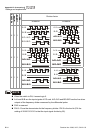
J3
A+, A-, B+, B-,
Z+, Z-
Sine line driver input
(incremental signal)
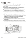
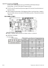
0
0
0
360 el.
0
90 el.
0
A
B
Z
0.8....1.2Vss
(~
~
1Vss; Z =120 )
0
0.2V....0.85V
(~
~
0.5V; Z =120 )
0