


Chapter 4 Parameters|
4-30 Revision Nov. 2008, VLE1, SW V1.03
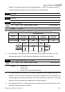
01-04 2nd Output Voltage Setting Unit: 0.1
Control
mode
VF VFPG
Settings 230V series 0.1 to 255.0V Factory Setting: 5.0
460V series 0.1 to 510.0V Factory Setting: 10.0
01-05 3rd Output Frequency Setting Unit: 0.01
Control
mode
VF VFPG
Factory setting: 0.50
Settings 0.00~120.00Hz
01-06 3rd Output Voltage Setting Unit: 0.1
Control
mode
VF VFPG
Settings 230V series 0.1 to 255.0V Factory Setting: 5.0
460V series 0.1 to 510.0V Factory Setting: 10.0
01-07 4th Output Frequency Setting Unit: 0.01
Control
mode
VF VFPG SVC FOCPG TQCPG
Settings 0.00~120.00Hz Factory Setting: 0.00
01-08 4th Output Voltage Setting Unit: 0.1
Control
mode
VF VFPG
Settings 230V series 0.1 to 255.0V Factory Setting: 0.0
460V series 0.1 to 510.0V Factory Setting: 0.0
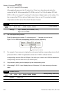
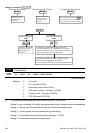
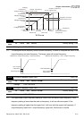
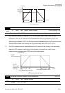
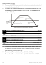
V/f curve setting is usually set by the motor’s allowable loading characteristics. Pay special
attention to the motor’s heat dissipation, dynamic balance, and bearing lubricity, if the loading
characteristics exceed the loading limit of the motor.
For the V/f curve setting, it should be Pr.01-01≥ Pr.01-03≥ Pr.01-05≥ Pr.01-07. There is no
limit for the voltage setting, but a high voltage at the low frequency may cause motor damage,
overheat, stall prevention or over-current protection. Therefore, please use the low voltage at
the low frequency to prevent motor damage.