


Chapter 2 Installation and Wiring|
2-12 Revision Nov. 2008, VLE1, SW V1.03
Terminal
Symbol
Terminal Function
Factory Settings (SINK)
ON: Connect to DCM
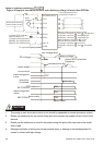
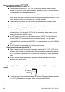
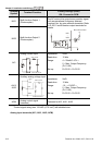
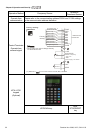
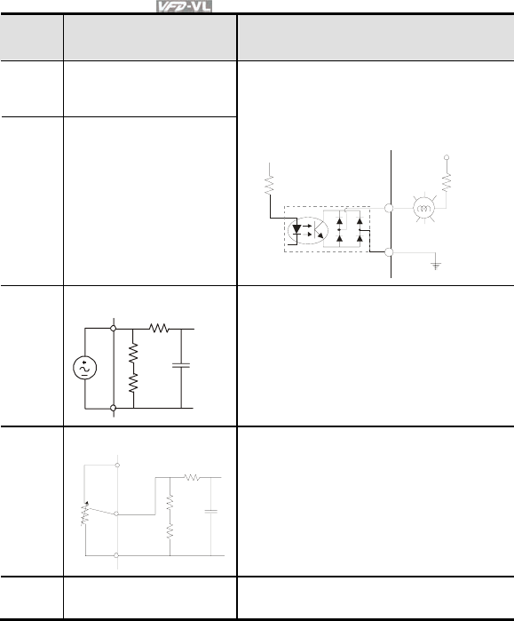
MO1
Multi-function Output 1
(Photocoupler)
MO2
Multi-function Output 2
(Photocoupler)
The AC motor drive output every monitor signal,
such as operational, frequency attained,
overload, etc. by open collector transistor. Refer
to Pr.03.01 multi-function output terminals for
details.
MO1
~
MO2
MCM
Max: 48Vdc/50m
A
internal circuit
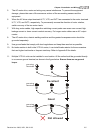
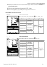
ACI
Analog current Input
ACM
ACI
internal circuit
ACI circuit
Impedance: 250
Resolution: 12 bits
Range: 4 ~ 20mA/0~10V =
0 ~ Max. Output Frequency
(Pr.01-00)
Set-up: Pr.03-00 ~ Pr.03-02
AUI1/
AUI2
Auxiliary analog voltage input
+10V
|
-10V
AUI
ACM
AUI circuit
internal circuit
Impedance: 2m
Resolution: 12 bits
Range: -10 ~ +10VDC =
0 ~ Max. Output Frequency
(Pr.01-00)
Set-up: Pr.03-00 ~ Pr.03-02
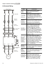
ACM
Analog control signal
(common)
Common for ACI, AUI1, AUI2
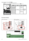
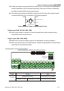
*Control signal wiring size: 18 AWG (0.75 mm
2
) with shielded wire.
Analog input terminals (ACI, AUI1, AUI2, ACM)