


Chapter 4 Parameters|
4-44 Revision Nov. 2008, VLE1, SW V1.03
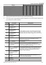
Settings Functions Descriptions
3
Desired Frequency
Attained 1 (Pr.02-25)
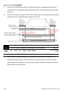
Active when the desired frequency (Pr.02-25) is attained.
4
Desired Frequency
Attained 2 (Pr.02-27)
Active when the desired frequency (Pr.02-27) is attained.
5
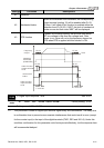
Zero Speed (frequency
command)
Active when frequency command =0. (the drive should be at
RUN mode)
6
Zero Speed with Stop
(frequency command)
Active when frequency command =0 or stop.
7
Over Torque (OT1)
(Pr.06-05~06-07)
Active when detecting over-torque. Refer to Pr.06-05 (over-
torque detection selection-OT1), Pr.06-06 (over-torque
detection level-OT1) and Pr.06-07 (over-torque detection
time-OT1).
8
Over Torque (OT2)
(Pr.06-08~06-10)
Active when detecting over-torque. Refer to Pr.06-08 (over-
torque detection selection-OT2), Pr.06-09 (over-torque
detection level-OT2) and Pr.06-10 (over-torque detection
time-OT2).
9 Drive Ready
Active when the drive is ON and no abnormality detected.
10
User-defined Low-
voltage Detection
Active when the DC Bus voltage is too low. (refer to Pr.06-00
low voltage level)
11 Malfunction Indication
Active when fault occurs (except Lv stop).
12
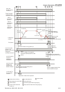
Mechanical Brake
Release (Pr.02-29,
Pr.02-30)
When drive runs after Pr.02-29, it will be ON. This function
should be used with DC brake and it is recommended to use
contact ”b”(N.C).
13 Overheat (Pr.06-14)
Active when IGBT or heat sink overheats to prevent OH turn
off the drive. (refer to Pr.06-14)
14 Brake Chopper Signal
The output will be activated when the drive needs help
braking the load. A smooth deceleration is achieved by using
this function. (refer to Pr.07-00)
15
Motor-controlled
Magnetic Contactor
Output
Active when the setting is set to 15.
16 Slip Error (oSL)
Active when the slip error is detected.
17 Malfunction indication 1 Activate after 10ms when fault occurs (except Lv stop).
18 Reserved
19
Brake Chopper Output
Error
Active when the brake chopper error is detected.