


Chapter 4 Parameters|
4-100 Revision Nov. 2008, VLE1, SW V1.03
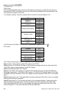
10-08 Encoder Slip Detection Time
Unit: 0.1
Control
mode
VFPG SVC FOCPG FOCPM
Factory Setting: 0.5
Settings 0.0 to 10.0 sec
10-09
Encoder Stall and Slip Error Treatment
Control
mode
VFPG SVC FOCPG FOCPM
Factory Setting: 2
Settings 0 Warn and keep operating
1 Warn and RAMP to stop
2 Warn and COAST to stop
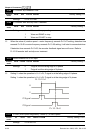
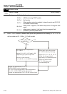
When the value of (rotation speed – motor frequency) exceeds Pr.10-07 setting, detection time
exceeds Pr.10-08 or motor frequency exceeds Pr.10-05 setting, it will start to accumulate time.
If detection time exceeds Pr.10-06, the encoder feedback signal error will occur. Refer to
Pr.10-09 encoder stall and slip error treatment.
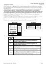
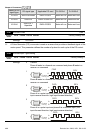
10-10 Mode Selection for UVW Input
Control
mode
VFPG FOCPG TQCPG FOCPM
Factory Setting: 0
Settings 0 Z signal is at the falling edge of U-phase
1 Z signal is at the rising edge of U-phase
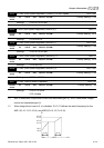
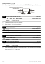
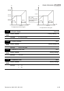
Setting 0: when the operation is U->V->W, Z signal is at the falling edge of U-phase.
Setting 1: when the operation is U->V->W, Z signal is at the rising edge of U-phase.
U
V
Pr.10-10=1
Pr.10-10=0
Z Signal
Z Signal
10-11 ASR (Auto Speed Regulation) Control (P) of Zero Speed Unit: 0.1
Control
mode
VF VFPG SVC FOCPG FOCPM
Factory Setting: 100.0
Settings 0.0 to 500.0%