


Chapter 2 Installation and Wiring|
Revision Nov. 2008, VLE1, SW V1.03 2-7
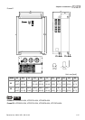
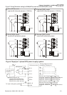
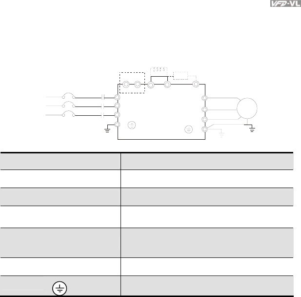
2.3 Main Circuit
2.3.1 Main Circuit Connection
Non-fuse breaker
(NFB)
Brak e res istor
(Optional)
Motor
R(L1)
S(L2)
T(L3)
R
S
T
U(T1)
V(T2)
W(T3)
IM
3~
MC
E
E
+1 +2/B1
B2
+
-
EPS
*
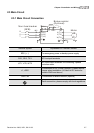
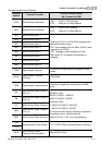
Terminal Symbol Explanation of Terminal Function
EPS (+, -) For emergency power or backup power supply
R/L1, S/L2, T/L3 AC line input terminals
U/T1, V/T2, W/T3
AC drive output terminals for connecting 3-phase
induction motor
+1, +2/B1
Connections for DC Choke (optional). Please remove
jumper when installation. (It is built in DC choke for
models 22kW and above
)
+2/B1, B2 Connections for Brake Resistor (optional)
Earth connection, please comply with local regulations.