


Chapter 4 Parameters|
Revision Nov. 2008, VLE1, SW V1.03 4-23
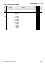
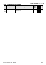
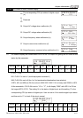
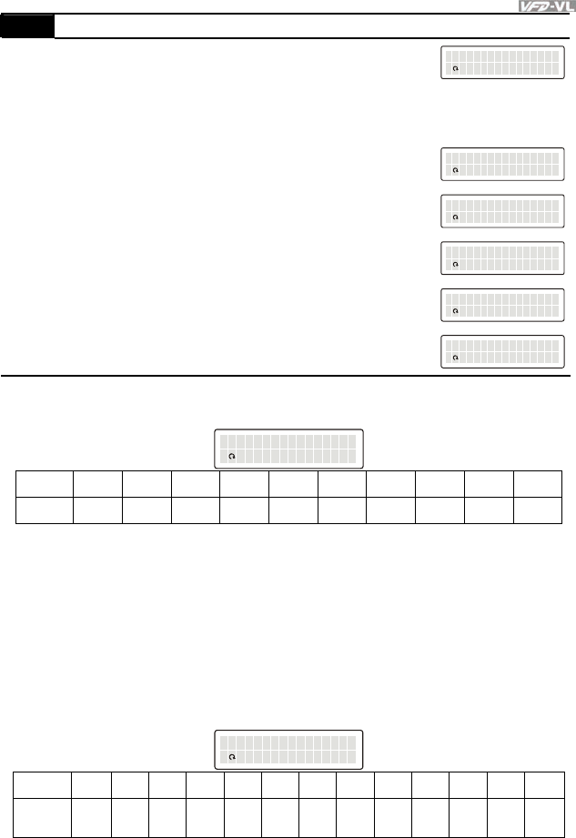
00-04 Content of Multi-Function Display
20
The corresponding CPU pin status of digital output
(o.)
DU: POEEin aSt t Eus
ESEEEE FEE FFF EE
EE
21
|
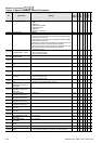
23
Reserved
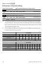
24 Output AC voltage when malfunction (8)
EU: orr Vr E tou EEEE
ESEEEE EEE 00. Ec
aV
25 Output DC voltage when malfunction (8.)
EU: orr Vr E sbu EEEE
ESEEEE 5E246. Ec
dV
26 Output frequency when malfunction (h)
EU: orr Fr E tou EEEE
ESEEEE 0EE 0.0 EE
zH
27 Output current when malfunction (4)
EU: orr Cr E rur e Ent
ESEEEE 0EE 0.0 sp
mA
28 Output frequency command when malfunction (h.)
EU: orr Fr E dcm EEEE
ESEEEE 0EE 0.0 sp
mA
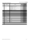
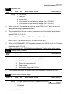
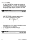
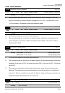
It is used to display the content when LED U is ON. It is helpful for getting the AC motor drive’s
status by this parameter.
DU: OI E ON/ EFF S tta
ESEEEE 0EE 608 EE
EE
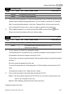
Terminal MI8 MI7 MI6 MI5 MI4 MI3 MI2 MI1 REV FWD
Status 0 0 1 0 0 0 0 1 1 0
0: OFF, 1: ON
MI1: Pr.02-01 is set to 1 (multi-step speed command 1)
MI8: Pr.02-08 is set to 8 (the 1st, 2nd acceleration/deceleration time selection)
If REV, MI1 and MI8 are ON, the value is 0000 0000 1000 0110
2
in binary and 0086H in HEX.
At the meanwhile, if Pr.00-04 is set to “14” or “17”, it will display “0086” with LED U is ON on
the keypad KPVL-CC01. The setting 14 is the status of digital input and the setting 17 is the
corresponding CPU pin status of digital input. User can set to 14 to monitor digital input status
and then set to 17 to check if the wire is normal.
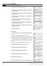
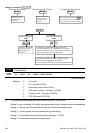
DU: OOE ON/ EFF S tta
ESEEEE 0EE 100 EE
EE
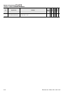
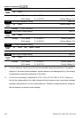
Terminal MO10 MO9 MO8 MO7 MO6 MO5 MO4 MO3 MO2 MO1 MRA RA MO10
Status
0 0 0 0 1 0 0 0 0 1 1 0 0