


Chapter 4 Parameters|
Revision Nov. 2008, VLE1, SW V1.03 4-89
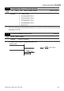
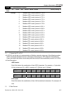
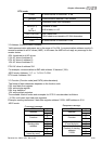
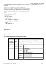
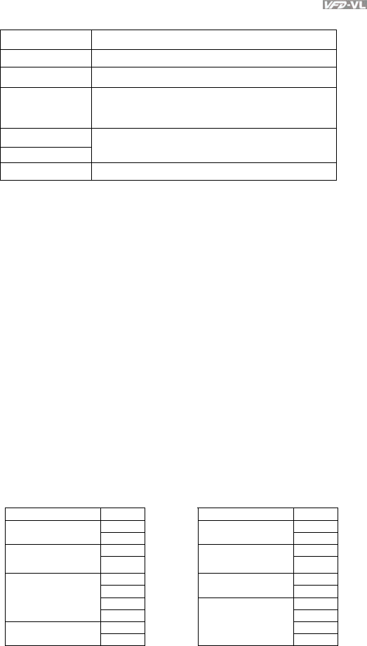
RTU mode:
START A silent interval of more than 10 ms
Address Communication address: 8-bit address
Function
Command code: 8-bit command
DATA (n-1)
to
DATA 0
Contents of data:
n×8-bit data, n<=16
CRC CHK Low
CRC CHK High
CRC check sum:
16-bit check sum consists of 2 8-bit characters
END A silent interval of more than 10 ms
3.2 Address (Communication Address)
Valid communication addresses are in the range of 0 to 254. A communication address equal to 0,
means broadcast to all AC drives (AMD). In this case, the AMD will not reply any message to the
master device.
00H: broadcast to all AC drives
01H: AC drive of address 01
0FH: AC drive of address 15
10H: AC drive of address 16
:
FEH: AC drive of address 254
For example, communication to AMD with address 16 decimal (10H):
ASCII mode: Address=’1’,’0’ => ‘1’=31H, ‘0’=30H
RTU mode: Address=10H
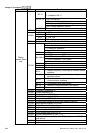
3.3 Function (Function code) and DATA (data characters)
The format of data characters depends on the function code.
03H: read data from register
06H: write single register
08H: loop detection
10H: write multiple registers
The available function codes and examples for VFD-VL are described as follows:
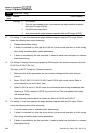
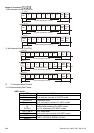
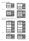
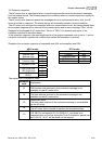
(1) 03H: multi read, read data from registers.
Example: reading continuous 2 data from register address 2102H, AMD address is 01H.
ASCII mode:
Command message:
Response message:
STX ‘:’ STX ‘:’
‘0’ ‘0’
Address
‘1’
Address
‘1’
‘0’ ‘0’
Function
‘3’
Function
‘3’
‘2’ ‘0’
‘1’
Number of data
(Count by byte)
‘4’
‘0’ ‘1’
Starting data
address
‘2’ ‘7’
‘0’ ‘7’ Number of data
(count by word)
‘0’
Content of starting
address
2102H
‘0’