


Chapter 2 Installation and Wiring|
Revision Nov. 2008, VLE1, SW V1.03 2-13
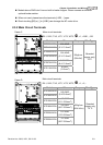
Analog input signals are easily affected by external noise. Use shielded wiring and keep it
as short as possible (<20m) with proper grounding. If the noise is inductive, connecting
the shield to terminal ACM can bring improvement.
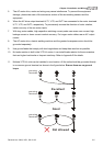
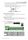
If the analog input signals are affected by noise from the AC motor drive, please connect
a capacitor and ferrite core as indicated in the following diagrams:
C
A
CI/AUI1/AUI2
ACM
ferrite core
wind each wires 3 times or more around the core
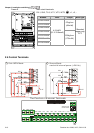
Digital inputs (FWD, REV, MI1~MI8, COM)
When using contacts or switches to control the digital inputs, please use high quality
components to avoid contact bounce.
Digital outputs (MO1, MO2, MCM)
Make sure to connect the digital outputs to the right polarity, see wiring diagrams.
When connecting a relay to the digital outputs, connect a surge absorber or fly-back diode
across the coil and check the polarity.
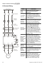
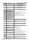
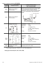
The specification for the control terminals
The Position of External Terminals
+10V
MO1
MO2
MI3
MI4
MI7
MI6
COM ACMAUI1
ACI
MCM
MRC
RA
MRA
RC
RB
REV
MI2
FWD
MI1
AUI2
MI5
MI8
-10V
Sink/Source
mode switch
+E24VDCM
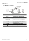
Frame Torque Wire
8 kgf-cm (6.9 in-lbf) 22-14 AWG (0.3-2.1mm
2
)
C, D, E
Terminal: 0V/24V 1.6 kgf-com(1.4 in-lbf) 30-16 AWG (0.051-1.3mm
2
)