


Chapter 2 Installation and Wiring|
2-4 Revision Nov. 2008, VLE1, SW V1.03
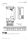
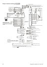
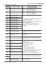
EPS/+
R/L1
S/L2
T/L3
EPS/-
MI1~8
COM
1
2
3
1
2
3
48Vdc (230V Series)
96Vdc (460V Series)
3
~
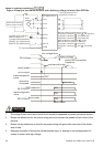
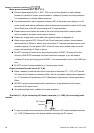
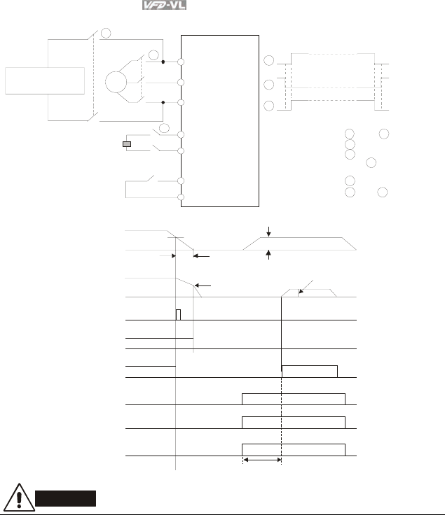
Before inputting emergency power,
magnetic contactor and are ON and
magnetic contactor should be OFF.
Magnetic contactor should be ON
after magnetic contactor is ON.
Before removing battery and turn
magnetic contactor to be ON,
magnetic contactor and should be
OFF.
Timing diagram of M.C.
(magnetic contact or)
AC motor drive
Main
power
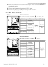
To input emergency power
250VDC (for 230V series)
500VDC (for 460V series)
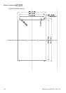
Specifications for
1-phase UPS and battery
1-phase UPS or battery
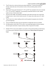
Figure 4 Apply to two batteries with main battery voltage is lower than 280Vd
c
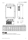
1 3
1
3
2
3
1
2
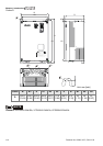
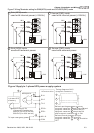
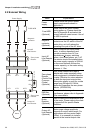
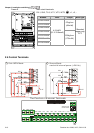
DC voltage
low voltage level
battery voltage
free run
motor speed
error output
operation
command
electromagnetic
valve
about 1 min.
mechanical brake
OFF
ON
ON
ON
about 2 sec
.
electromagnetic
valve
MI-COM=43
default EPS operation
frequency
MO-COM=9
drive ready
EPS detection
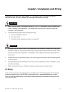
CAUTION!
1. The wiring of main circuit and control circuit should be separated to prevent erroneous actions.
2. Please use shield wire for the control wiring and not to expose the peeled-off net in front of the
terminal.
3. Please use the shield wire or tube for the power wiring and ground the two ends of the shield
wire or tube.
4. Damaged insulation of wiring may cause personal injury or damage to circuits/equipment if it
comes in contact with high voltage.