


Chapter 2 Installation and Wiring|
Revision Nov. 2008, VLE1, SW V1.03 2-3
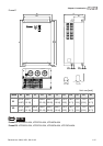
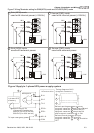
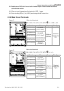
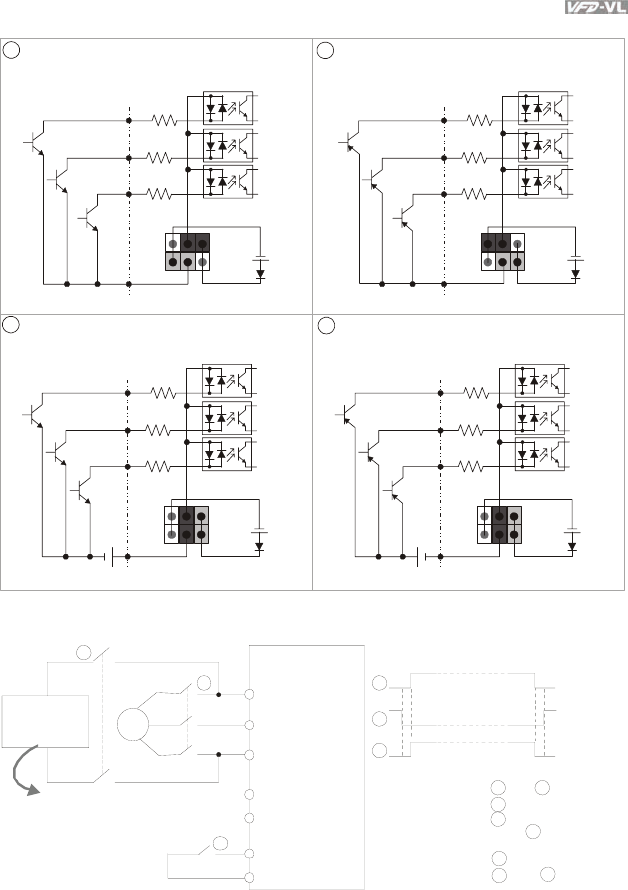
Figure 2 Wiring/Terminals setting for SINK(NPN) mode and SOURCE(PNP) mode
3
1
Sink (NPN) mode
Source (PNP) mode
2
4
Sink (NPN) mode
Source (PNP) mode
used with internal power (+24Vdc) used with internal power (+24Vdc)
used with external power
used with external power
COM
MI1
+24V
MI2
MI8
~
COM
MI1
+24V
MI2
MI8
~
COM
MI1
+24V
+
MI2
MI8
~
COM
MI1
+24V
+
MI2
MI8
~
250VDC (for 230V series)
500VDC (for 460V series)
3
~
EPS/+
R/L1
S/L2
T/L3
EPS/-
MI1~8
COM
1
2
3
1
2
3
AC motor drive
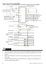
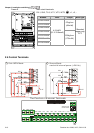
Timing diagram of M.C.
(magnetic contact or)
Main power
1-phase UPS
or battery
Specifications for
1-phase UPS and battery
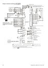
Figure 3 Apply to 1-phase UPS power supply syste
m
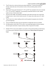
To input emergency power
Before inputting emergency power,
magnetic contactor and are ON and
magnetic contactor should be OFF.
Magnetic contactor should be ON
after magnetic contactor is ON.
Before removing battery and turn
magnetic contactor to be ON,
magnetic contactor and should be
OFF
.
1
3
1
3
2
3
1
2