


Chapter 4 Parameters|
Revision Nov. 2008, VLE1, SW V1.03 4-43
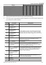
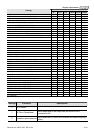
Control Mode
Settings
VF VFPG SVC FOCPG TQCPG FOCPM
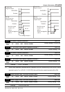
2: Operation speed attained
○ ○ ○ ○ ○ ○
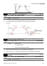
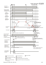
3: Desired frequency attained 1 (Pr.02-25)
○ ○ ○ ○
○
4: Desired frequency attained 2 (Pr.02-27)
○ ○ ○ ○
○
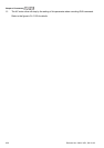
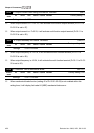
5: Zero speed (frequency command)
○ ○ ○ ○
○
6: Zero speed with stop (frequency command)
○ ○ ○ ○
○
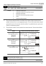
7: Over torque (OT1) (Pr.06-05~06-07)
○ ○ ○ ○ ○ ○
8: Over torque (OT2) (Pr.06-08~06-10)
○ ○ ○ ○ ○ ○
9: Drive ready
○ ○ ○ ○ ○ ○
10: User-defined Low-voltage Detection (LV)
○ ○ ○ ○ ○ ○
11: Malfunction indication
○ ○ ○ ○ ○ ○
12: Mechanical brake release (Pr.02-29, Pr.02-30)
○ ○ ○ ○ ○ ○
13: Overheat (Pr.06-14)
○ ○ ○ ○ ○ ○
14: Brake chopper signal
○ ○ ○ ○ ○ ○
15: Motor-controlled magnetic contactor output
○ ○ ○ ○ ○ ○
16: Slip error (oSL)
○ ○ ○ ○
○
17: Malfunction indication 1
○ ○ ○ ○ ○ ○
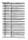
18: Reserved
19: Brake chopper output error
○ ○ ○ ○ ○ ○
20: Warning output
○ ○ ○ ○ ○ ○
21: Over voltage warning
○ ○ ○ ○ ○ ○
22: Over-current stall prevention warning
○ ○ ○
23: Over-voltage stall prevention warning
○ ○ ○ ○ ○ ○
24: Operation mode indication (Pr.00-150)
○ ○ ○ ○ ○ ○
25: Forward command
○ ○ ○ ○ ○ ○
26: Reverse command
○ ○ ○ ○ ○ ○
27: Output when current >= Pr.02-33
○ ○ ○ ○ ○ ○
28: Output when current < Pr.02-33
○ ○ ○ ○ ○ ○
29: Output when frequency >= Pr.02-34
○ ○ ○ ○ ○ ○
30: Output when frequency < Pr.02-34
○ ○ ○ ○ ○ ○
31-32: Reserved
33: Zero speed (actual output frequency)
○ ○ ○ ○
○
34: Zero speed with Stop (actual output frequency)
○ ○ ○ ○
○
35: Fault output option 1 (Pr.06-22)
○ ○ ○ ○ ○ ○
36: Fault output option 2 (Pr.06-23)
○ ○ ○ ○ ○ ○
37: Fault output option 3 (Pr.06-24)
○ ○ ○ ○ ○ ○
38: Fault output option 4 (Pr.06-25)
○ ○ ○ ○ ○ ○
39: Reserved
40: Speed attained (including zero speed)
○ ○ ○ ○
○
41: Reserved
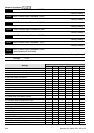
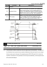
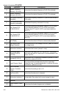
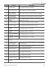
Settings Functions Descriptions
0 No Function
1 AC Drive Operational
Active when there is an output from the drive or RUN
command is ON.
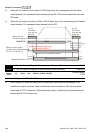
2 Operation speed attained
Active when the AC motor drive reaches the output frequency
setting.