


Chapter 4 Parameters|
Revision Nov. 2008, VLE1, SW V1.03 4-51
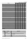
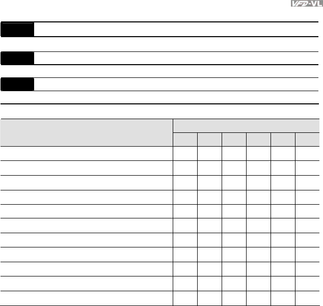
Group 3 Analog Input/Output Parameters
03-00
Analog Input 1 (AUI1)
Factory Setting: 1
03-01
Analog Input 2 (ACI)
Factory Setting: 0
03-02
Analog Input 3 (AUI2)
Factory Setting: 0
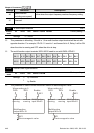
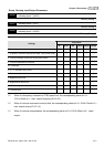
Control Mode
Settings
VF VFPG SVC FOCPG TQCPG FOCPM
0: No function
○ ○ ○ ○ ○ ○
1: Frequency command (torque limit under TQR control mode)
○ ○ ○ ○ ○ ○
2: Torque command (torque limit under speed mode)
○
3: Torque compensation command
○ ○ ○ ○ ○ ○
4-5: Reserved
6: P.T.C. thermistor input value
○ ○ ○ ○ ○ ○
7: Positive torque limit
○
○
8: Negative torque limit
○
○
9: Regenerative torque limit
○
○
10: Positive/negative torque limit
○
○
11: Preload Input
○
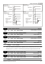
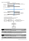
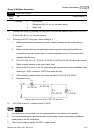
When it is frequency command or TQR speed limit, the corresponding value for 0~±
10V/4~20mA is 0 – max. output frequency(Pr.01-00)
When it is torque command or torque limit, the corresponding value for 0~±10V/4~20mA is 0 –
max. output torque (Pr.07-14).
When it is torque compensation, the corresponding value for 0~±10V/4~20mA is 0 – rated
torque.