


Chapter 3 Operation and Start Up|
3-6 Revision Nov. 2008, VLE1, SW V1.03
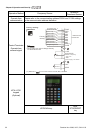
Settings of Pr.02-
01~02-08
14: Reserved
15: operation speed command form AUI1
16: operation speed command form ACI
17: operation speed command form AUI2
18: Emergency Stop (07-28)
19-23: Reserved
24: FWD JOG command
25: REV JOG command
26: Reserved
27: ASR1/ASR2 selection
28: Emergency stop (EF1) (Motor coasts to stop)
29-30: Reserved
31: High torque bias (by Pr.07-21)
32: Middle torque bias (by Pr.07-22)
33: Low torque bias (by Pr.07-23)
34-37: Reserved
38: Disable write EEPROM function
39: Torque command direction
40: Enable drive function
41: Reserved
42: Mechanical brake
43: EPS function
Refer to Pr.02-13~02-22 for setting external output terminals MO1~MO10.
Settings of Pr.02-
13~02-22
0: No function
1: Operation indication
2: Operation speed attained
3: Desired frequency attained 1 (Pr.02-25)
4: Desired frequency attained 2 (Pr.02-27)
5: Zero speed (frequency command)
6: Zero speed with stop (frequency command)
7: Over torque (OT1) (Pr.06-05~06-07)
8: Over torque (OT2) (Pr.06-08~06-10)
9: Drive ready
10: User-defined Low-voltage Detection (LV)
11: Malfunction indication
12: Mechanical brake release (Pr.02-29, Pr.02-30)
13: Overheat (Pr.06-14)
14: Brake chopper signal
15: Motor-controlled magnetic contactor output
16: Slip error (oSL)
17-18: Reserved