


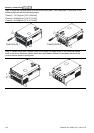

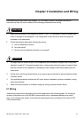

Chapter 2 Installation and Wiring|
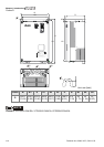
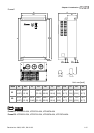
2-2 Revision Nov. 2008, VLE1, SW V1.03
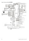
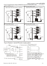
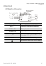
FWD
REV
MI1
MI2
MI3
MI4
MI6
MI5
MI7
U(T1)
V(T2)
W(T3)
IM/PM
1 2 3 4 5 6
*RS-485
To communicate to PC, it needs
to use converter (VFD-USB01 or
IFD8500).
R(L1)
S(L2)
T(L3)
NFB
R
S
T
RB
RC
+1 +2/B1
B2
RA
RB
RC
E
E
MC
SA
OFF
ON
MC
MC
E
1:+EV
2:GND
3:SG-
4:SG+
5:NC
6:NC
+
-
EPS
MI8(*1)
COM
+10V
AUI1/AUI2
*
ACI
ACM
E
4~20mA
A
PG Card (optional)
Line driver
PG
U
V
W
*
Fuse/NFB(No Fuse Breaker)
Brake resisto
r
(optional)
Motor
Brake resistor/Unit(optional)
Refer to Appendix B for the use of
special brake resistor/unit
Recommended Circuit
when power supply
is turned OFF by a
fault output
Factory setting:
SINK Mode
multifunction
terminals
incremental encoder
Factory
setting
Forward/STOP
Reverse/STOP
Multi-step 1
Multi-step 2
Multi-step 3
Multi-step 4
No function
(*1)
Digital Signal Common
No function
No function
No function
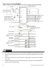
Please refer to the
following figure for wiring
of SINK mode and SOURCE
mode.
Power supply
+10V 20mA
-10V
Power supply
-10V 20mA
Master
Frequency
-10 to 10V
Main circuit (power) terminals
Control circuit terminals
Shielded leads & Cable
Multi-function contact
output 1 (Relay)
240VAC 3A
120VAC 3A
24VDC 3A
factory setting:
fault indication
MO1
MO2
MCM
MRA
MRC
Multi-function contact output 2 (Relay)
240VAC 3A
120VAC 3A
24VDC 3A
factory setting:
indicates that it is running
Multi-function contact output 3
(photocoupler)
48VDC 50mA
Multi-function contact output 4
(photocoupler)
Multi-function
Photocoupler Output
*
*
Terminal EPS is emergency power input terminal, refer to the following figure for details.
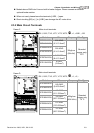
For PG card, refer to Appendix B for details.
PG Card (optional)
EMVL-PGABL
EMVL-PGABO
EMVL-PGH01
(*1) When JP1
on the control board is inserted, MI8 is disabled.
EMVL-IOD01
extension card
(optional)