


Chapter 4 Parameters|
Revision Nov. 2008, VLE1, SW V1.03 4-7
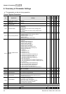
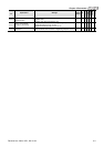
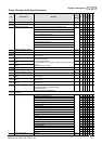
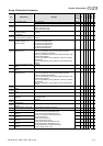
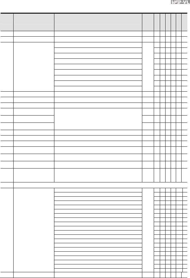
Group 3 Analog Input/Output Parameters
Pr. Explanation Settings
Factory
Setting
VF
VFPG
SVC
FOCPG
TQCPG
FOCPM
03-00
Analog Input 1 (AUI1) 0: No function 1
○ ○ ○ ○ ○ ○
03-01
Analog Input 2 (ACI) 1: Frequency command (torque limit under TQR control mode) 0
○ ○ ○ ○ ○ ○
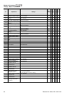
03-02
Analog Input 3 (AUI2) 2: Torque command (torque limit under speed mode) 0
○
3: Torque compensation command
○ ○ ○ ○ ○ ○
4-5: Reserved
6: P.T.C. thermistor input value
○ ○ ○ ○ ○ ○
7: Positive torque limit
○ ○
8: Negative torque limit
○ ○
9: Regenerative torque limit
○ ○
10: Positive/negative torque limit
○ ○
11: Preload Input
○
03-03
Analog Input Bias 1 (AUI1)
-100.0~100.0%
0.0
○ ○ ○ ○ ○ ○
03-04
Analog Input Bias 2 (ACI)
-100.0~100.0%
0.0
○ ○ ○ ○ ○ ○
03-05
Analog Input Bias 3 (AUI2)
-100.0~100.0%
0.0
○ ○ ○ ○ ○ ○
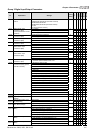
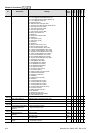
03-06
Positive/negative Bias Mode
(AUI1)
0
○ ○ ○ ○ ○ ○
03-07
Positive/negative Bias Mode
(ACI)
0
○ ○ ○ ○ ○ ○
03-08
Positive/negative Bias Mode
(AUI2)
0: Zero bias
1: Lower than bias=bias
2: Greater than bias=bias
3: The absolute value of the bias voltage while serving as the
center
4: Serve bias as the center
0
○ ○ ○ ○ ○ ○
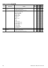
03-09
Analog Input Gain 1 (AUI1)
-500.0~500.0%
100.0
○ ○ ○ ○ ○ ○
03-10
Analog Input Gain 2 (ACI )
-500.0~500.0%
100.0
○ ○ ○ ○ ○ ○
03-11
Analog Input Gain 3 (AUI2)
-500.0~500.0%
100.0
○ ○ ○ ○ ○ ○
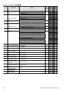
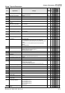
03-12
Analog Input Delay Time
(AUI1)
0.00~2.00 sec
0.01
○ ○ ○ ○ ○ ○
03-13
Analog Input Delay Time
(ACI)
0.00~2.00 sec
0.01
○ ○ ○ ○ ○ ○
03-14
Analog Input Delay Time
(AUI2)
0.00~2.00 sec
0.01
○ ○ ○ ○ ○ ○
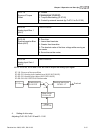
03-15
Loss of the ACI Signal 0: Disable
1: Continue operation at the last frequency
2: Decelerate to 0Hz
3: Stop immediately and display E.F.
0
○ ○ ○ ○ ○ ○
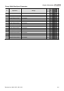
03-16
Reserved
0: Output frequency (Hz)
○ ○ ○ ○ ○ ○
1: Frequency command (Hz)
○ ○ ○ ○ ○ ○
03-17
Analog Output Selection 1
2: Motor speed (RPM)
0
○ ○ ○ ○ ○ ○
3: Output current (rms)
○ ○ ○ ○ ○ ○
4: Output voltage
○ ○ ○ ○ ○ ○
5: DC Bus Voltage
○ ○ ○ ○ ○ ○
6: Power factor
○ ○ ○ ○ ○ ○
7: Power
○ ○ ○ ○ ○ ○
8: Output torque
○ ○ ○ ○ ○ ○
9: AUI1
○ ○ ○ ○ ○ ○
10: ACI
○ ○ ○ ○ ○ ○
11: AUI2
○ ○ ○ ○ ○ ○
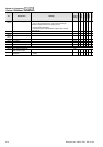
12: q-axis current
○ ○ ○ ○ ○ ○
13: q-axis feedback value
○ ○ ○ ○ ○ ○
14: d-axis current
○ ○ ○ ○ ○ ○
15: d-axis feedback value
○ ○ ○ ○ ○ ○
16: q-axis voltage
○ ○ ○ ○ ○ ○
17: d-axis voltage
○ ○ ○ ○ ○ ○
18: Torque command
○ ○ ○ ○ ○ ○
19-20: Reserved
03-18
Analog Output Gain 1 0~200.0% 100.0
○ ○ ○ ○ ○ ○