


Chapter 4 Parameters|
Revision Nov. 2008, VLE1, SW V1.03 4-99
5
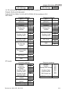
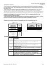
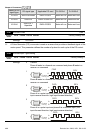
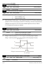
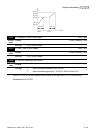
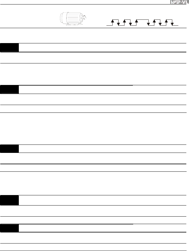
Single-phase input
Forward
running
A
It is helpful for the stable control by inputting correct pulse type.
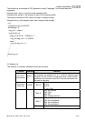
10-03
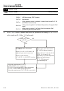
Encoder Feedback Fault Treatment (PGF1, PGF2)
Control
mode
VFPG FOCPG TQCPG
Factory Setting: 2
Settings 0 Warn and keep operation
1 Warn and RAMP to stop
2 Warn and stop operation
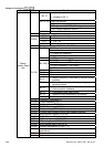
10-04 Detection Time for Encoder Feedback Fault Unit: 0.1
Control
mode
VFPG FOCPG TQCPG FOCPM
Factory Setting: 1.0
Settings 0.0 to 10.0 sec
When PG loss, encoder signal error, pulse signal setting error or signal error, if time exceeds
the detection time for encoder feedback fault (Pr.10-04), the PG signal error will occur. Refer
to the Pr.10-03 for encoder feedback fault treatment.
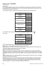
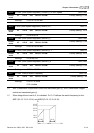
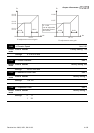
10-05 Encoder Stall Level (PGF5) Unit: 1
Control
mode
VFPG SVC FOCPG FOCPM
Factory Setting: 115
Settings 0 to 120% (0: disable)
This parameter determines the maximum encoder feedback signal allowed before a fault
occurs. (max. output frequency Pr.01-00 =100%)
10-06 Encoder Stall Detection Time Unit: 0.1
Control
mode
VFPG SVC FOCPG FOCPM
Factory Setting: 0.1
Settings 0.0 to 2.0 sec
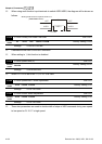
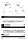
10-07 Encoder Slip Range (PGF7) Unit: 1
Control
mode
VFPG SVC FOCPG FOCPM
Factory Setting: 50
Settings 0 to 50% (0: disable)